
Method for reducing positioning torque of stator permanent magnetic type electric machine based on rotor auxiliary slot

A positioning torque and auxiliary groove technology, applied in wind power generation, magnetic circuit static parts, magnetic circuit rotating parts, etc., can solve the problem of increasing the manufacturing cost of the motor and the difficulty of the processing technology, the method of reducing the positioning torque is complex, and the performance of the motor Influence and other problems, to achieve the effect of compact structure, increased manufacturing cost and high power density

Inactive Publication Date: 2009-07-22
环一军
View PDF0 Cites 4 Cited by
  • Summary
  • Abstract
  • Description
  • Claims
  • Application Information

AI Technical Summary

Problems solved by technology

[0003] However, since the stator permanent magnet motor adopts a doubly salient pole structure and has the function of gathering magnetism, its air gap magnetic density is relatively large, resulting in a relatively prominent positioning torque, which causes a large torque ripple during the operation of the motor. Limits its application in wind power generation and servo drives
On the other hand, the methods for reducing the positioning torque for traditional rotor permanent magnet motors are relatively complicated and difficult to implement, which increases the manufacturing cost of the motor and the difficulty of processing technology, and at the same time has different degrees of influence on the performance of the motor

Method used


Image

  • Method for reducing positioning torque of stator permanent magnetic type electric machine based on rotor auxiliary slot
  • Method for reducing positioning torque of stator permanent magnetic type electric machine based on rotor auxiliary slot
  • Method for reducing positioning torque of stator permanent magnetic type electric machine based on rotor auxiliary slot

Examples


Embodiment Construction

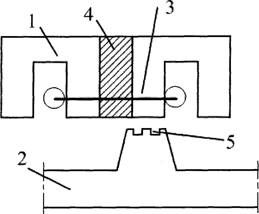
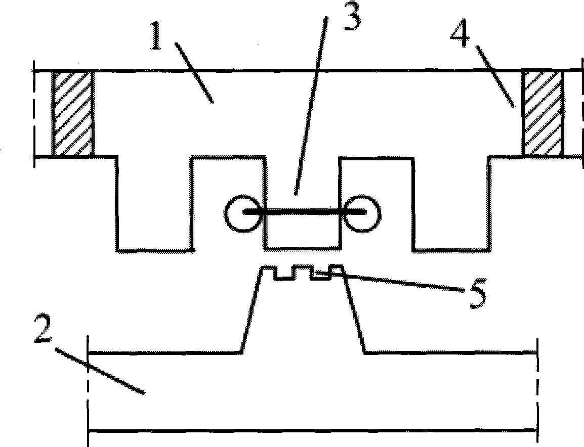
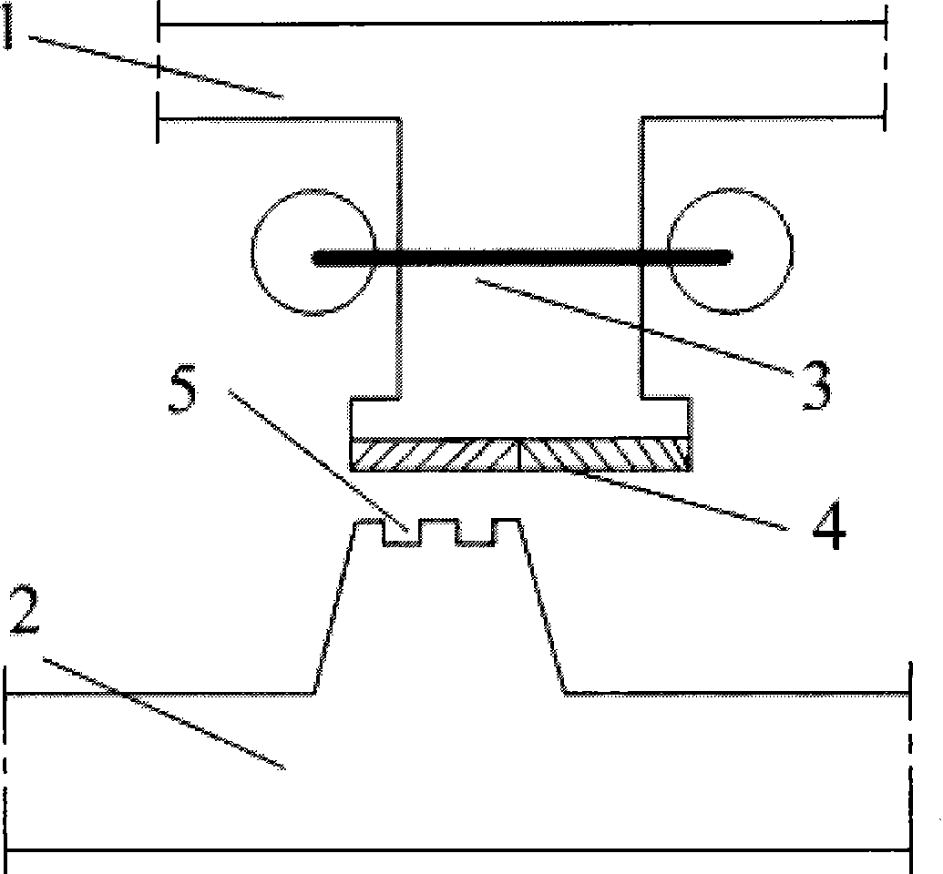
[0015] To figure 1 In the example, the magnetic flux switching doubly salient permanent magnet motor of the present invention includes a stator 1 and a rotor 2. The rotor 2 is located inside or outside the stator 1. Both the stator 1 and the rotor 2 have a doubly salient structure, in which the stator 1 consists of 12 U The stator 1 is composed of three-phase concentrated windings 3 and 12 permanent magnets 4, the rotor 2 has 10 rotor teeth, and each rotor tooth has 2 auxiliary slots 5.

[0016] Since the stator slots are 12 and the rotor teeth are 10, the frequency of the fundamental component of the positioning torque generated is 60, and the corresponding mechanical period is 6 degrees. After the harmonic analysis of the positioning torque of the motor, it is found that the second harmonic of the high-order harmonic components of the positioning torque is relatively large. Therefore, two auxiliary slots are selected on the rotor teeth to weaken the second harmonic component of...


PUM


Abstract

The invention discloses a method for reducing the locating moment of a permanent-magnet type motor of a stator based on an auxiliary groove of a rotor. The auxiliary groove is arranged on the rotor to increase upper harmonic component generated by magnetic conductance of an air gap tooth space, so that the fundamental frequency of the generated locating moment is increased, while the amplitude is correspondingly reduced. As the dimension of the auxiliary groove of the rotor is optimally designed, the idle load electric potential of the motor can be guaranteed when the locating moment is reduced, and the performance index such as torque output capability and the like can not be influenced. In the structure, the invention maintains the advantages of being compact and simple, good in robustness and suitable for high speed running of the permanent-magnet type motor of the stator; the volume of the motor is not needed to be additionally increased, and on the contrary, the magnet core quantity of the rotor can be reduced. Compared with other ways used for reducing the locating moment, the technical method is simple, convenient and effective, has low cost and is especially suitable for the permanent-magnet type motor of the stator, thus the type of motor has better application prospect in the fields such as a direct drive type aerogenerator, hybrid vehicle, etc.

Description

Technical field: [0001] The invention relates to a generator manufacturing technology, in particular to a technology for reducing the positioning torque of a stator permanent magnet motor. Background technique: [0002] As the country with the largest reserve of rare earth materials in the world, my country has vigorously studied and promoted the application of various new types of permanent magnet motors represented by rare earth permanent magnet motors, which has important theoretical significance and application value. Whether for power generation or electric operation, new permanent magnet motors with high efficiency, high torque (power) density and low loss are showing a trend of accelerated development. For a long time, research hotspots at home and abroad have been concentrated on rotor permanent magnet motors represented by surface mount, plug-in and in-line types. However, this type of motor will have a series of problems during the design and actual operation, which are...

Claims


Application Information

Patent Timeline
Patent Type & Authority Applications(China)
IPC IPC(8): H02K1/17H02K1/24
CPCY02E10/725Y02E10/72
Inventor 环剑斌花为郑自明苏申科唐震东陆建松
Owner 环一军
Learn More