Method and apparatus for generating multi-frequency microwave signal source
A high-frequency microwave and signal method technology, applied in electromagnetic wave transmission systems, electrical components, transmission systems, etc., can solve problems such as difficulty in increasing the frequency of microwave signals
- Summary
- Abstract
- Description
- Claims
- Application Information
AI Technical Summary
Problems solved by technology
Method used
Image
Examples
Embodiment 1
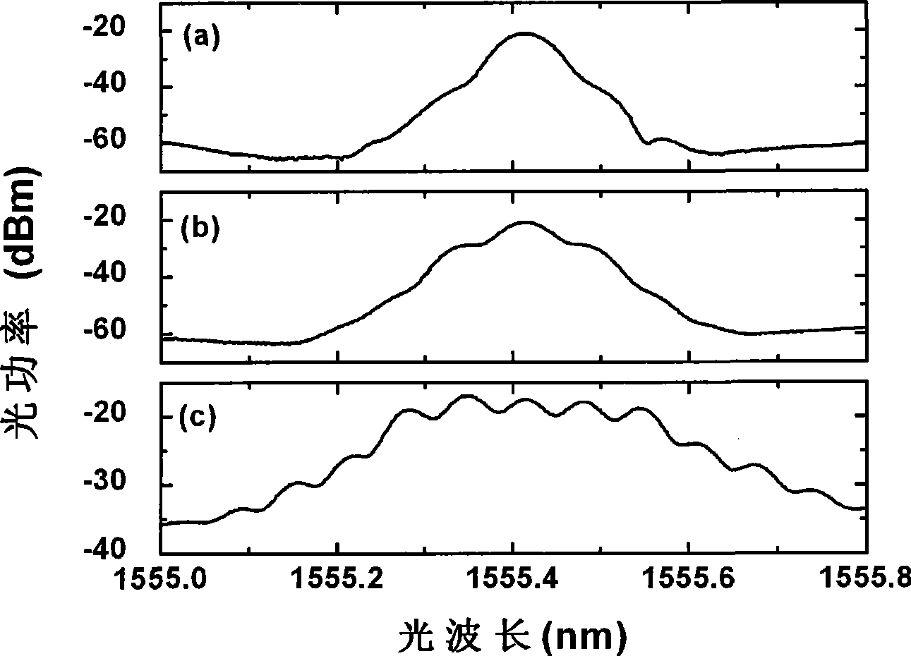
[0027] The effect of four-wave mixing in highly nonlinear fibers can be achieved by image 3 To illustrate. image 3 (a) is the spectrum diagram of the optical carrier generated by the laser before entering the intensity modulator. When a microwave driving signal with a frequency of 8GHz is applied to the intensity modulator, multiple optical sidebands will be generated on both sides of the optical carrier, such as image 3 (b) shown. However, the number of optical sidebands generated by direct modulation is limited, and the intensity difference between each sideband is relatively large, which will affect the frequency number and intensity balance of the microwave signal generated by the beat frequency. The modulated optical carrier is incident into the highly nonlinear fiber for four-wave mixing, through this effect, the energy exchange between each optical sideband is fully performed, thereby increasing the number of output light waves and reducing the distance between eac...
Embodiment 2
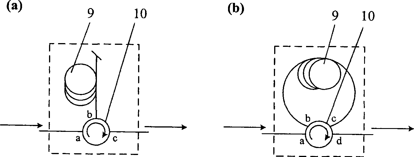
[0029] use figure 2 The first-order Brillouin frequency shift module shown in (a) uses the laser output with a wavelength of 1555.4nm as the incident light. The combined spectrum of first-order Stokes light as Figure 4 As shown in (a), the frequency difference between the two peaks is 11.8GHz. When they are incident on the photodetector to generate optical beat frequency, the obtained multi-frequency microwave signal spectrum is as follows Figure 5 As shown, its center frequency is 11.8GHz. Figure 5 The frequency of the driving signal used in (a) is 1 GHz, Figure 5 The frequency of the driving signal used in (b) is 500MHz, and the frequency interval of the multi-frequency microwave signal is the same as that of the driving microwave signal, which are 1GHz and 500MHz, respectively.
Embodiment 3
[0031] use figure 2 The secondary Brillouin frequency shift module shown in (b) uses the laser with a wavelength of 1555.4nm output by the laser as the incident light. The combined spectrum of first-order Stokes light as Figure 4 As shown in (b), the frequency difference between the two peaks is 21.6GHz. When they are incident on the photodetector to generate optical beat frequency, the obtained multi-frequency microwave signal spectrum is as follows: Image 6 As shown, its center frequency is 21.6GHz. Image 6 The frequency of the driving signal used in (a) is 1 GHz, Image 6 The frequency of the driving signal used in (b) is 500 MHz, and the frequency interval of the multi-frequency microwave signal is the same as that of the driving microwave signal, which are 1 GHz and 500 MHz, respectively.
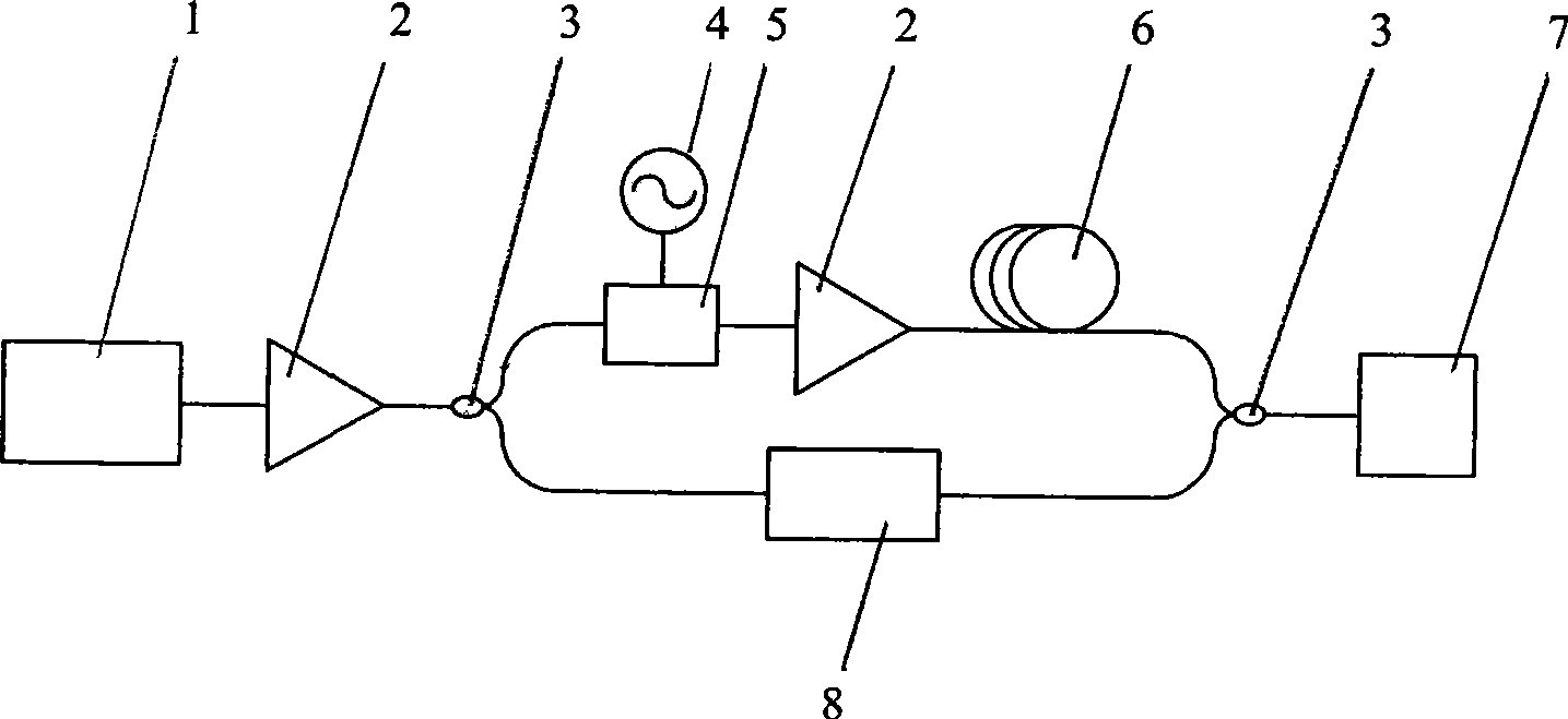
[0032]In the present invention, lasers, optical amplifiers, couplers / splitters, low-frequency microwave signal sources, intensity modulators, highly nonlinear optical fibers, p...
PUM
 Abstract
Description
Claims
Application Information
 - R&D
- Intellectual Property
- Life Sciences
- Materials
- Tech Scout
- Unparalleled Data Quality
- Higher Quality Content
- 60% Fewer Hallucinations
Browse by: Latest US Patents, China's latest patents, Technical Efficacy Thesaurus, Application Domain, Technology Topic, Popular Technical Reports.
© 2025 PatSnap. All rights reserved.Legal|Privacy policy|Modern Slavery Act Transparency Statement|Sitemap|About US| Contact US: help@patsnap.com


