Rolling guide and guard

A guide device and guide roller technology, applied in the field of material-oriented devices, can solve the problems of decreased stability of the guide device, high processing difficulty, limited adjustment range, etc., and achieve reduced guide cost, low processing difficulty, and stability Good results

Inactive Publication Date: 2009-07-15
HEFEI BAISHENG SCI & TECH
View PDF0 Cites 7 Cited by
  • Summary
  • Abstract
  • Description
  • Claims
  • Application Information

AI Technical Summary

Problems solved by technology

In order to meet the guiding requirements of wires and rods of various sizes and specifications, the rolling guide device is usually equipped with a spacing adjustment mechanism for the guide rollers. At present, the eccentric shaft structure and the cam structure are commonly used, and the eccentric shaft structure is used to adjust the guide roller. When the roller spacing is used, on the one hand, the processing cost of the eccentric shaft is relatively high; on the other hand, the adjustment range is very limited when the eccentric shaft is used alone to adjust the guide roller spacing; when the cam structure is used, due to the complex structure of the cam, the processing difficulty is relatively large. Moreover, its rigidity is poor, which will easily lead to a decrease in the stability of the guide device.

Method used


Image

  • Rolling guide and guard
  • Rolling guide and guard
  • Rolling guide and guard

Examples


Embodiment Construction

[0009] The present invention will be further described below in conjunction with accompanying drawing:

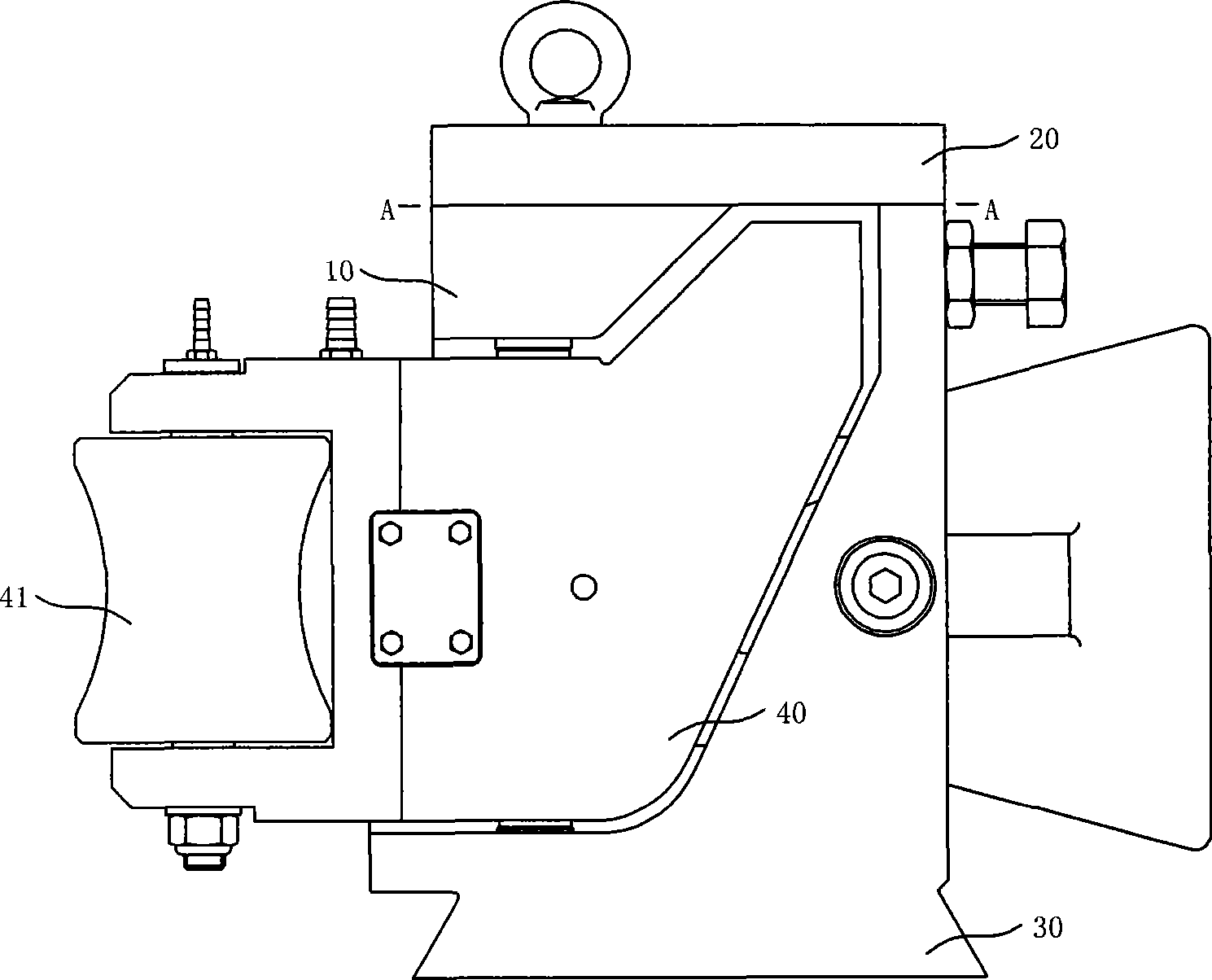
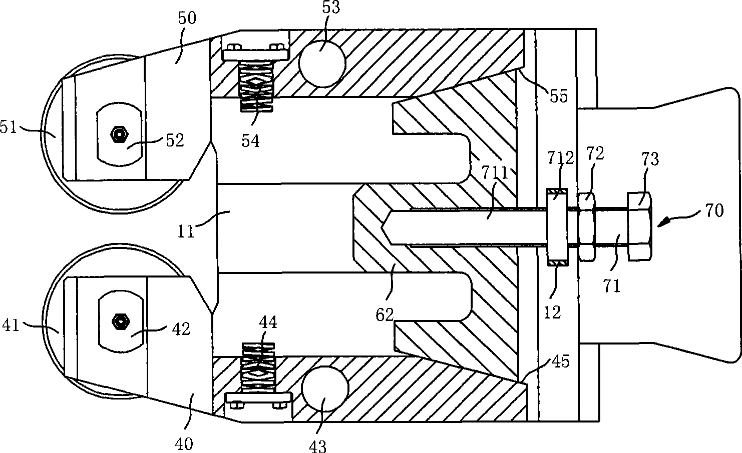
[0010] Such as figure 1 , figure 2 The shown rolling guide device includes a guide box 10 with a cover plate 20 on its upper part and a base 30 on its lower part. A channel for blanks or finished products to pass is formed between the cover plate 20 and the base 30. The cover plate 20 and the base 30 both sides are provided with left and right guide wheel arms 40,50 arranged in the front and rear direction, the front ends of the left and right guide wheel arms are provided with guide rollers 41,51, and the rotary shafts of guide rollers 41,51 42,52 center is positioned at vertical direction, and left and right guide wheel arm 40,50 is hinged between cover plate 20 and base 30 by rotating shaft 43,53, and rotating shaft 43,53 and the rotating shaft 42,52 of guide roller 41,51 parallel. The front ends of the left and right guide wheel arms 40, 50 are respectively provided...


PUM


Abstract

The invention relates to a device for guiding the wire-shaped working materials and the bar-shaped working materials, in particular to a roller guide and guard unit which comprises a guide and guard case body, a cover plate and a base. The rear ends of a left idler pulley arm and a right idler pulley arm are provided with opening regulating mechanisms, each opening regulating mechanism comprises a wedge-shaped regulating block fixed on the guide and guard case body, and both lateral wedge surfaces of the wedge-shaped regulating block are respectively attached to the lateral surfaces inside the rear ends of the left idler pulley arm and the right idler pulley arm. With the technical scheme, both sides of the roller guide and guard unit are limited in a rolling way by a front guide roller group and a rear guide roller group after the wire-shaped working materials and the bar-shaped working materials enter the roller guide and guard unit, and the wire-shaped working materials and the bar-shaped working materials can be smoothly guided to pass through. Furthermore, because the rear ends of the left idler pulley arm and the right idler pulley arm are provided with opened regulating mechanisms, and each opened regulating mechanism adopts the wedge-shaped regulating block, the left idler pulley arm and the right idler pulley arm are driven by the wedge-shaped regulating blocks moving front and back to rotate, thereby the invention realizes the regulation of the opening degree of the guide rollers. In addition, because the processing difficulty of the wedge-shaped regulating blocks is low, the guide and guard cost is reduced, and because the rigidity of the wedge-shaped regulating blocks is high, the guide and guard stability is good.

Description

technical field [0001] The invention relates to a device for guiding materials in the shape of wires and rods suitable for rolling mills, in particular to a rolling guide device. Background technique [0002] Because the rolling guide device has significant advantages such as low friction and long service life, it has become an inevitable trend to replace sliding guides. In order to meet the guiding requirements of wires and rods of various sizes and specifications, the rolling guide device is usually equipped with a spacing adjustment mechanism for the guide rollers. At present, the eccentric shaft structure and the cam structure are commonly used, and the eccentric shaft structure is used to adjust the guide roller. When the roller spacing is used, on the one hand, the processing cost of the eccentric shaft is relatively high; on the other hand, the adjustment range is very limited when the eccentric shaft is used alone to adjust the guide roller spacing; when the cam stru...

Claims


Application Information

Patent Timeline
Patent Type & Authority Applications(China)
IPC IPC(8): B21B39/14
Inventor 娄霆李运强
Owner HEFEI BAISHENG SCI & TECH
Why Eureka
Try Eureka