
Stray current tester and stray current analysis method

A technology of stray current and analysis method, applied in the direction of measuring current/voltage, reasoning method, analyzing materials, etc., can solve the problems of cathodic protection system interference, lack of intuition, and inability to display graphically, to improve efficiency and accuracy degree of effect

Inactive Publication Date: 2009-07-08
UNIV OF ELECTRONICS SCI & TECH OF CHINA
View PDF0 Cites 19 Cited by
  • Summary
  • Abstract
  • Description
  • Claims
  • Application Information

AI Technical Summary

Problems solved by technology

Moreover, if there is already DC stray current interference on the pipeline, the superimposed AC stray current interference will cause depolarization of the metal surface, resulting in increased corrosion
AC stray current can also accelerate the aging of the insulation layer and may interfere with the normal operation of the cathodic protection system
[0008] 2) The display of measurement data is mainly character display or pointer reading, which lacks intuition and cannot be displayed graphically, which brings inconvenience to on-site application
Due to the analysis of stray currents, such as stray current sources, possible inflow points and outflow points, stray current drainage measures, etc., it is not related to the pipeline embedding environment (seabed, desert, hills, soil acidity and alkalinity, temperature, pipeline anti-corrosion coating, etc.) layer material, type of cathodic protection system, etc.) has a strong relationship, and the analysis methods of existing equipment and technology have not realized computer-aided analysis based on artificial intelligence

Method used


Image

  • Stray current tester and stray current analysis method
  • Stray current tester and stray current analysis method
  • Stray current tester and stray current analysis method

Examples


Embodiment

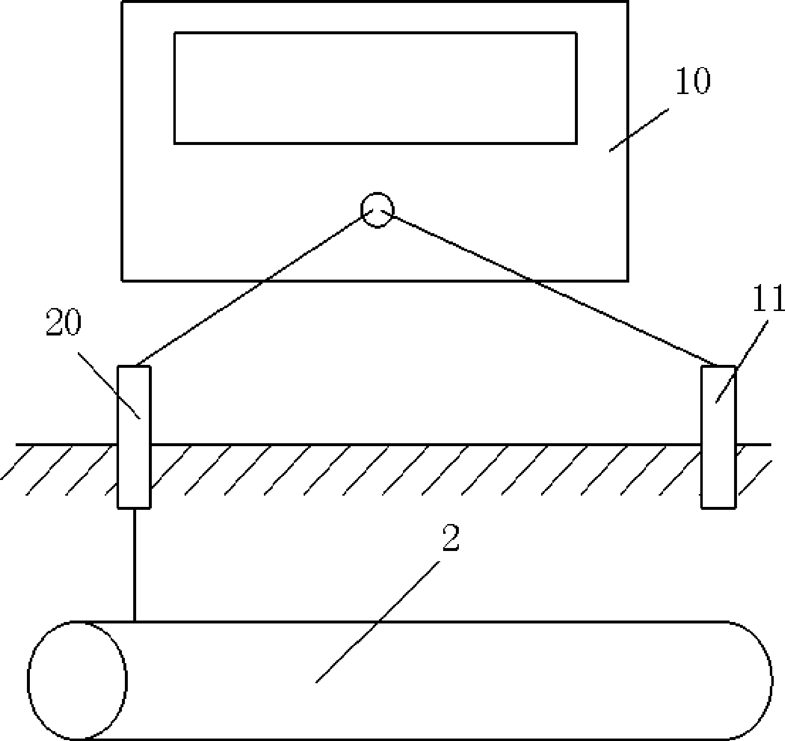
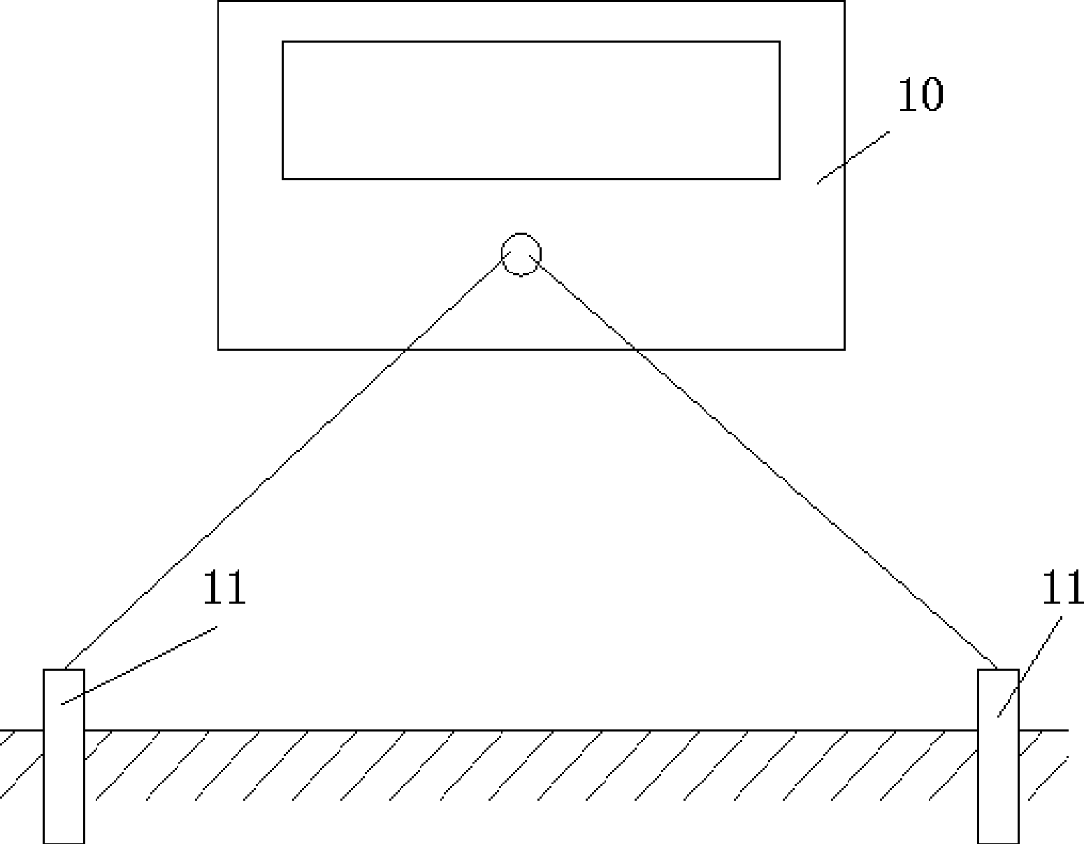
[0038] Such as Figure 4 , The stray current tester 10 is generally designed with 4 channels, each channel is connected to 2 electrodes 11, and each electrode is arranged in a straight line. Such as Figure 4 Connect the tester as shown, and measure the distance between each pair of electrodes. Use the keyboard on the instrument to input the distance between the channels corresponding to the test points one by one, and then start the gradient curve drawing function to test the voltage between each electrode in turn. Calculate the corresponding earth potential gradient, and display the earth potential gradient curve on the instrument in a graphical way, such as Figure 5 shown. The abscissa in the figure is the distance between the test point and the pipeline, and the ordinate is the potential gradient.

[0039] exist Figure 4 In the shown earth potential gradient measurement method, one electrode in each pair of electrodes is replaced by a test pile of a metal pipe (gener...


PUM


Abstract

The invention relates to buried pipeline protection technology, in particular to stray current detection and analysis technology of buried pipelines. The invention discloses a stray current tester and a stray current analysis method, which can reflect the distribution situation of stray current on the ground more comprehensively and intuitively, and provide a scientific evidence for the protection of the buried pipelines. The stray current tester comprises a data acquisition device and at least two detection channels, wherein each detection channel can measure a path of voltage; the data acquisition device is used for recording each path of voltage and drawing a graph according to recorded voltage data to display; and the voltage comprises a direct current component and an alternating current component. The stray current analysis method utilizes a fuzzy expert system of a computer to comprehensively analyze acquired various data, and an obtained result is more accurate and comprehensive.

Description

technical field [0001] The invention relates to buried pipeline protection technology, in particular to buried pipeline stray current detection and analysis technology. Background technique [0002] Buried pipelines include various oil pipelines, gas pipelines and various water supply / drainage pipelines, most of which are metal pipelines. In order to improve the corrosion resistance of metal pipes and prolong their service life, the outer layer of metal pipes generally has an anti-corrosion coating. Moreover, in order to further improve the anti-corrosion ability, cathodic protection measures are also adopted. Generally, a voltage is applied to the metal pipeline so that the metal pipeline presents a negative potential (about -1.25 to -0.85V) to the ground. The specific value depends on the environment of the pipeline, the pipeline coating Layer type and quality and other factors). With the application and development of electric power technology, the electromagnetic envir...

Claims


Application Information

Patent Timeline
Patent Type & Authority Applications(China)
IPC IPC(8): G01R19/00G01N17/02G06N5/04
Inventor 黄琦张昌华陈勇刘群英易建波施泽钦陈奥林张海波
Owner UNIV OF ELECTRONICS SCI & TECH OF CHINA
Learn More