Mandrel structure of circular saw machine for preferably cutting timber in longitudinal direction

A circular saw machine and saw shaft technology, applied in the field of wood processing, can solve the problems of inability to optimize, high labor intensity, waste of raw material resources, etc.

Active Publication Date: 2009-07-08
JIANGSU JIANGJIA MACHINERY
View PDF0 Cites 3 Cited by
  • Summary
  • Abstract
  • Description
  • Claims
  • Application Information

AI Technical Summary

Problems solved by technology

[0003] Although the saw shaft of this circular saw machine with fixed saw blade spacing has the advantages of high production efficiency, easy control of the board width and easy guarantee of a given board size compared with single saw blade sawing equipment, but this kind of saw blade with fixed saw blade spacing The defects in the saw shaft of the circular saw machine are also obvious
First of all, it is impossible to choose the best sawing plan according to the characteristics of raw materials and sawing requirements with a fixed saw blade interval, but can only "copy" the corresponding board width according to the set saw blade interval, which only depends on the preset With a certain saw blade spacing, it is impossible to avoid defects such as knots or splits in the wood during the sawing process. This fixed sawing size is bound to be far from the best sawing plan, and the best sawing plan The characteristics of the given actual sawn timber should be considered, and the optimal sawing order should be determined according to the optimized mathematical method and reasonable collocation. Therefore, this unoptimizable sawing plan means that more sawing waste will be generated, low yield
Second, even if the existing multi-blade circ...

Method used


Image

  • Mandrel structure of circular saw machine for preferably cutting timber in longitudinal direction
  • Mandrel structure of circular saw machine for preferably cutting timber in longitudinal direction
  • Mandrel structure of circular saw machine for preferably cutting timber in longitudinal direction

Examples


Embodiment Construction

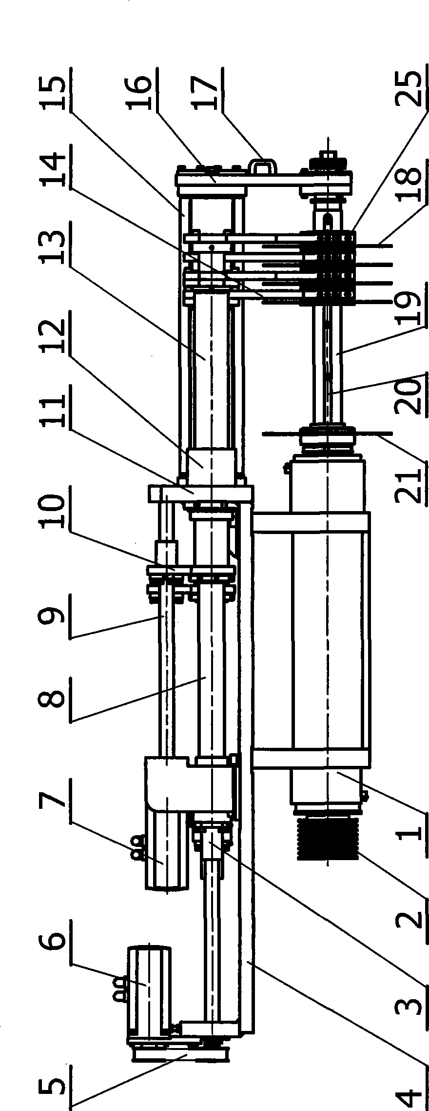
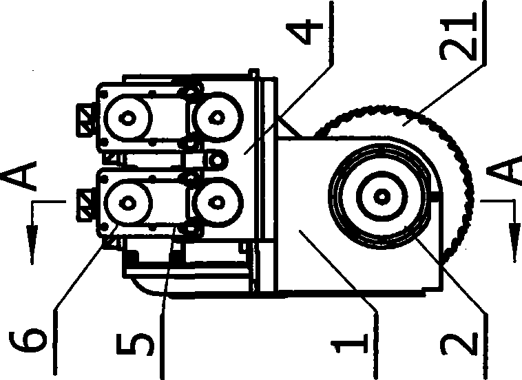
[0018] exist figure 1 , figure 2 and image 3 In the shown saw shaft structure, the saw shaft 19 is supported by rolling bearings on the saw shaft support 1, and the saw shaft support 1 is supported on the frame of the circular saw machine. One end of saw shaft 19 is equipped with saw shaft pulley 2, and saw shaft pulley 2 is connected with saw shaft drive motor transmission, on the other protruding end of saw shaft 19 and saw shaft pulley 2 assembly end relative, successively is equipped with A piece of fixed circular saw blade 21 and four saw blade sliding sleeves 25, fixed circular saw blade 21 can only do rotary sawing with saw shaft. The shaft surface of the saw shaft 19 is symmetrically provided with two saw shaft sliding keys 20 along the length direction, and the saw shaft sliding keys 20 are slidingly matched with two sliding key slots in the shaft hole of the saw blade sliding sleeve 25 . A moving circular saw blade 18 is housed on each saw blade sliding sleeve 2...


PUM


Abstract

The present invention discloses a saw shaft structure of optimized longitudinal cutting circular sawing machine, which comprises a saw shaft and a saw shaft base that is used for supporting the saw shaft. The saw shaft is at least sleeved with a sawblade sliding sleeve which can move along the axial direction and rotate along with the saw shaft. The sawblade sliding sleeve is at least fixedly installed with a movable circular saw blade which is movably connected with a circular saw blade shifting fork. The circular saw blade shifting fork is connected with a screw pair. The saw shaft is at least fixedly installed with a fixed circular saw blade and is at least fixedly installed with a saw shaft driving key. The shaft hole of sawblade sliding sleeve is at least internally provided with a driving key groove that is corresponding with the saw shaft driving key. The saw shaft structure can realize the axial sliding adjustment to the circular saw blade conveniently and flexibly. Longitudinally material cutting can be executed according to an optimal cutting plan. The saw shaft structure also has higher material yielding rate and production efficiency, and is widely used in various multi-blade circular sawing machine.

Description

technical field [0001] The invention relates to the technical field of wood processing, in particular to equipment for longitudinally cutting and cutting wood, and in particular to the improvement of the saw shaft structure of a multi-blade circular saw machine. Background technique [0002] Longitudinal cutting and cutting of sawn timber such as wood is a common process operation in wood processing, and multi-blade circular saws are common process equipment for longitudinally cutting wood. This type of multi-blade circular saw machine with longitudinal section function is above the feeding chain plate supported on the machine base, and a pressing mechanism including front and rear feeding rollers is set, and a pressing mechanism is set between the front and rear feeding rollers. A circular saw blade saw shaft is arranged, and a plurality of circular saw blades are housed on the circular saw blade saw shaft. Each circular saw blade is set on the saw shaft at a fixed interva...

Claims


Application Information

Patent Timeline
IPC IPC(8): B27B7/00B27B7/04
Inventor 朱志林蒋坤尧陈斌臧景平张伟
Owner JIANGSU JIANGJIA MACHINERY
Why Eureka
Try Eureka