Eureka AIR delivers breakthrough ideas for toughest innovation challenges, trusted by R&D personnel around the world.

Continuous plasma flow ignition exciter

A technology of plasma flow and exciter, applied in combustion ignition, incandescent ignition, machine/engine, etc., can solve the problem of serious electromagnetic radiation, affecting the performance and life of ignition device, etc.

Inactive Publication Date: 2009-06-24
HARBIN ENG UNIV
View PDF1 Cites 5 Cited by
  • Summary
  • Abstract
  • Description
  • Claims
  • Application Information

AI Technical Summary

Problems solved by technology

Although semiconductor surface discharge ignition can obtain a large ignition power, due to the life of the semiconductor, it directly affects the performance and life of the entire ignition device, and the electromagnetic radiation is quite serious.

Method used


Image

  • Continuous plasma flow ignition exciter
  • Continuous plasma flow ignition exciter
  • Continuous plasma flow ignition exciter

Examples


Embodiment Construction

[0022] The present invention is described in more detail below in conjunction with accompanying drawing example:

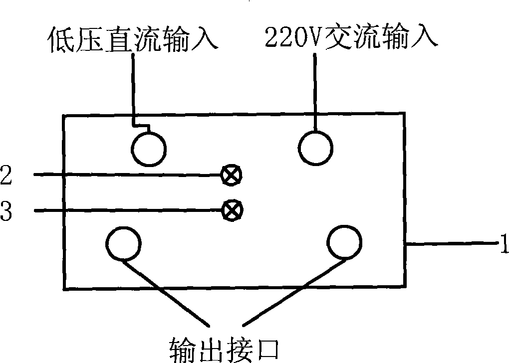
[0023] combine figure 1 , figure 1 It is a schematic diagram of the external connection of the continuous plasma flow ignition actuator of the present invention. Its external interface and indicator light mainly include: a 220V AC input interface, a low-voltage DC control input interface, a working indicator light, a fault indicator light, and an output interface. The number of output interfaces of the exciter can be determined according to the number of ignition sources determined by factors such as gas turbine power and fuel. According to the number of output interfaces, the exciter module can be expanded. For example, if one exciter is designed to have 2 outputs, if 4 ignition sources are required, two exciters, 4 sets of plasma generators and high-voltage ignition cables are equipped.

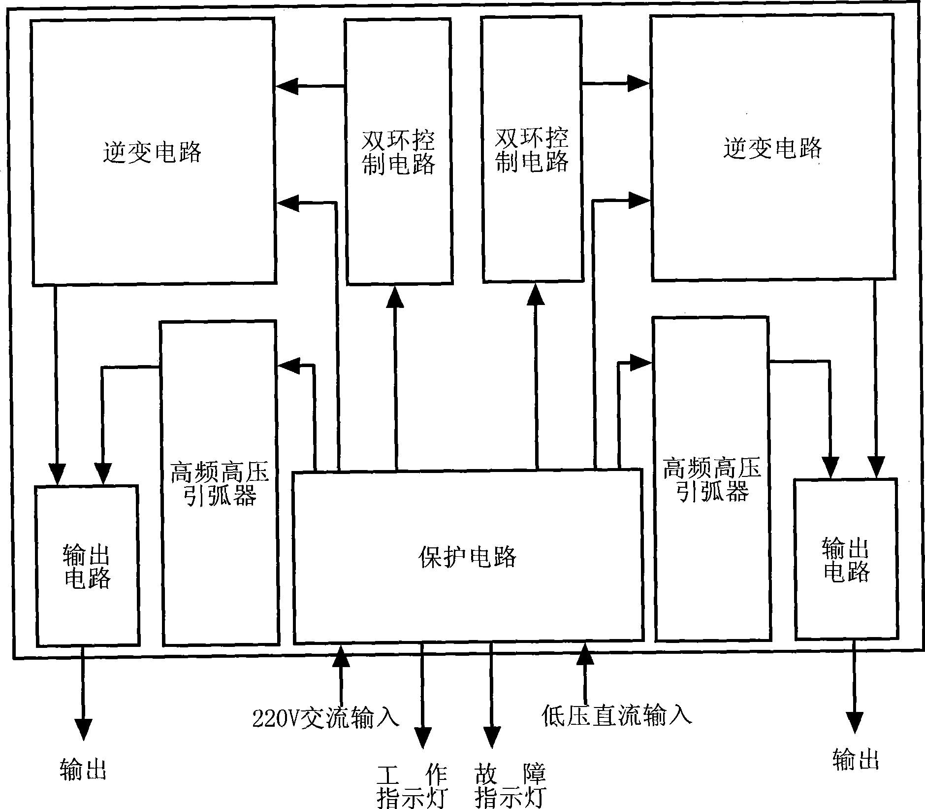
[0024] figure 2 It is a schematic diagram of the internal structure m...


PUM


Abstract

The invention provides a continuous plasma jet ignition exciter unit, comprising a protective circuit, an inverter circuit, a dual loop control circuit, an output circuit and a high frequency high voltage arc generator. The ignition exciter unit is used for providing low current excitation for a plasma jet ignition exciter unit of a gas turbine. The ignition exciter unit adopts a modular design of high frequency switching power supply, thus improving efficiency, and reducing volume and weight; a PWM is adopted to modulate and control impulse width, and the output is stable low current; the dual loop control circuit is adopted to control working mode by means of stabilizing current and restricting voltage, and the output is characterized by steep fall of voltage and constant current of electric current, so that the ignition exciter unit avoids being burned when the output short-cuts.

Description

(1) Technical field [0001] The invention relates to an ignition control device for a heat energy and power device, in particular to a continuous plasma flow ignition exciter suitable for a gas turbine. (2) Background technology [0002] Nowadays, gas turbines have been widely used and developed in many fields such as aviation, ships, and power generation due to their advantages such as high power, small weight and size, and high efficiency. During the start-up process of a gas turbine, ignition is critical. The success rate of ignition will be directly related to the safe and reliable operation of the whole device. [0003] At present, the commonly used gas turbine ignition methods include electric spark ignition and semiconductor surface discharge ignition. The ignition energy of the electric spark point is low and the ignition delay is long. Although the semiconductor surface discharge ignition can obtain a large ignition power, due to the life of the semiconductor, it d...

Claims


Application Information

Patent Timeline
Patent Type & Authority Applications(China)
IPC IPC(8): F02C7/266F23Q7/00F23Q7/22
Inventor 杨家龙郑洪涛谭智勇陈明敏李智明周春良
Owner HARBIN ENG UNIV
Why Eureka
Eureka Blog
Learn More