
Method for making metallic surface pattern

A metal surface and manufacturing method technology, applied in the field of pattern making on metal surfaces, can solve the problems of limited transfer area, inability to achieve discontinuous pattern masking, low efficiency, etc., and achieve the effects of better adaptability and improved pattern transfer efficiency

Inactive Publication Date: 2009-06-17
LENOVO (BEIJING) CO LTD
View PDF0 Cites 19 Cited by
  • Summary
  • Abstract
  • Description
  • Claims
  • Application Information

AI Technical Summary

Problems solved by technology

In the process of realizing the present invention, the inventor found the following technical problems in the prior art. Usually, silk screen printing can only achieve pattern transfer on a plane, while pad printing transfer is only suitable for curved surfaces with small curvature, and the transfer area is limited, so it cannot be realized on complex curved surfaces. pattern transfer; while the spraying transfer process requires a spraying fixture, the spraying fixture is made into a hollow shape with a preset pattern, and the spraying fixture is attached to the metal surface, and the corrosion-resistant material is sprayed and then etched. Or directly etch to obtain a pattern on the metal surface
But the disadvantage of this spraying transfer is that the area covered by the spraying jig must remain geometrically continuous, and the masking of discontinuous patterns cannot be realized, so the form of the pattern is greatly limited
In the traditional mold etching process, the pattern transfer can also be realized by film lamination. Although the plane film lamination can approximately transfer the plane pattern to the non-developable surface through complicated manual repair, this process scheme is more suitable for single piece delivery
Once batch supply is required, the efficiency of manual repair is too low, and the labor and material investment is too high
[0003] This shows that the above-mentioned existing method for making a pattern on a curved metal surface still has many defects, and needs to be further improved urgently.

Method used


Image

  • Method for making metallic surface pattern

Examples


Embodiment Construction

[0026] Hereinafter, in conjunction with the accompanying drawings and preferred embodiments, the specific implementation, features, and effects of the method for manufacturing a metal surface pattern proposed in the present invention will be described in detail as follows.

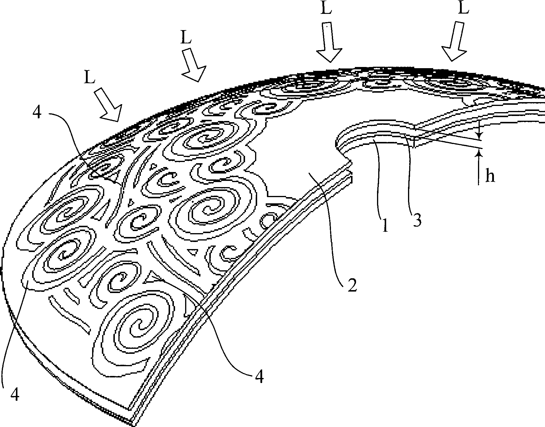
[0027] See figure 1 What is shown is a schematic configuration diagram of an embodiment of the present invention, which is shown as a moment in the process of implementing the method. In the method for making a metal surface pattern in this implementation, the metal surface 1 is an aluminum alloy product surface, the material of which is A1050 (or A1052), the surface is spherical or ellipsoidal, and a layer of photosensitive glue is coated on the metal surface 1 The photosensitive glue layer 3 is formed, and the photosensitive glue used is SY-10 type photosensitive glue provided by Taiwan Liuhe Chemical. The thickness of the photosensitive adhesive layer 3 is 0.5-0.8 mm, the coating area is the entire range of...


PUM


Abstract

The invention relates to a method for manufacturing a metal surface pattern, which comprises: coating photosensitive resist on a metal surface to form a photosensitive adhesive layer; covering an enclosure provided with a preset pattern on a metal surface cover; providing irradiation light to the metal surface from the outside of the enclosure, and exposing the photosensitive resist; removing the unexposed photosensitive resist; and etching, coloring or coating the metal surface. The metal surface is a curved surface (a curved surface which can not be expanded), the enclosure has a curved surface which is the same as the metal surface or a similar curved surface which is offset and magnified, and the curved surface has a distance from the photosensitive adhesive layer. The enclosure is made of transparent material, and the preset pattern is a nontransparent pattern. The method is suitable for the curved surface which has complex shape and large curvature and can not be folded, and has no limit for the preset pattern; the method improves pattern transfer efficiency greatly, so that the method can be used for batch production of metal products; and the method also solves the problem of difficult control for the tolerances of shape and size caused by deformation during the production of the metal products with the curved surfaces.

Description

Technical field [0001] The invention relates to a method for making patterns, in particular to a method for making patterns on a metal surface. Background technique [0002] There are many metal products, in order to increase the visual effect of their appearance, some patterns or patterns are usually designed on the surface of the metal products. The method of generating patterns on the metal surface generally adopts an etching process. For mass-produced metal products, it is necessary to design a pattern in advance, and then transfer the preset pattern to the metal surface by pattern transfer, and then use an etching process to etch according to the preset pattern on the metal surface. Thus, a metal product with a preset pattern is obtained. In the above method, transferring the preset pattern to the metal surface is a very important step, because whether the pattern transferred to the metal surface is intact and consistent with the preset pattern will directly affect the patte...

Claims


Application Information

Patent Timeline
IPC IPC(8): G03F7/00G03F1/14G03F1/00
Inventor 韩小勤谢予明
Owner LENOVO (BEIJING) CO LTD
Learn More