Hydrocarbon oil conversion method

A hydrocarbon oil and catalyst technology, applied in chemical instruments and methods, cracking, petroleum industry, etc., can solve the problem of not being able to have high hydrogen yield and hydrocarbon oil conversion rate at the same time, and achieve an increase in production and high hydrogen yield. Effect

Active Publication Date: 2009-06-17
CHINA PETROLEUM & CHEM CORP +1
View PDF3 Cites 15 Cited by
  • Summary
  • Abstract
  • Description
  • Claims
  • Application Information

AI Technical Summary

Problems solved by technology

[0005] The purpose of the present invention is to overcome the shortcomings that the existing hydrocarbon oil conversion method cannot have higher hydrogen production rate and hydrocarbon oil conversion rate and better product distribution at the same time, and provide a method that can simultaneously improve the hydrogen production rate and hydrocarbon oil conversion. Process for converting hydrocarbon oils with high efficiency and improved product distribution of hydrocarbon oil reaction products

Method used


Image

  • Hydrocarbon oil conversion method
  • Hydrocarbon oil conversion method

Examples


Embodiment 1

[0031] This example is used to illustrate the hydrocarbon oil conversion method provided by the present invention.

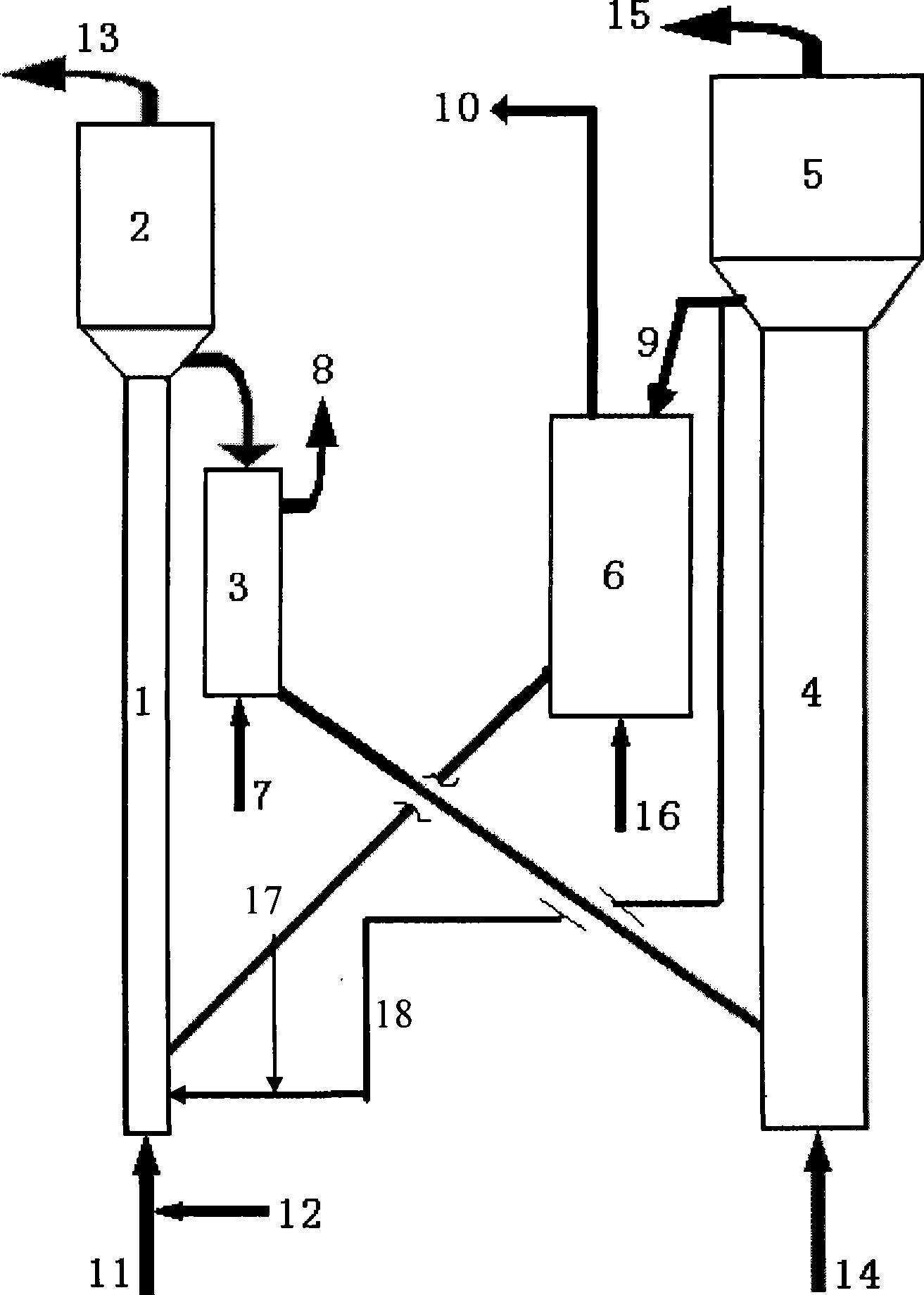
[0032] Such as figure 1 As shown, the catalyst is sent to the bottom of the riser reactor 1, hydrocarbon oil 11 and water vapor 12 are added from the bottom of the riser reactor 1, and the catalyst is contacted with the hydrocarbon oil to obtain reaction products and spent catalyst. The reaction conditions in the riser reactor 1 include: the reaction temperature is 480°C, the reaction time is 3 seconds, the weight ratio of catalyst to hydrocarbon oil is 5:1, the reaction pressure is 200 kPa (absolute pressure), water vapor and hydrocarbon The weight ratio of oil is 0.08:1. The coke content of the spent catalyst was 0.95% by weight of the total spent catalyst.

[0033] The reaction product 13 and the unborn catalyst are separated by the settler 2, and then the unborn catalyst is stripped by the stripper 3 and sent to the gasifier 4, and the mixed gas 14 of wate...

Embodiment 2

[0039] This example is used to illustrate the hydrocarbon oil conversion method provided by the present invention.

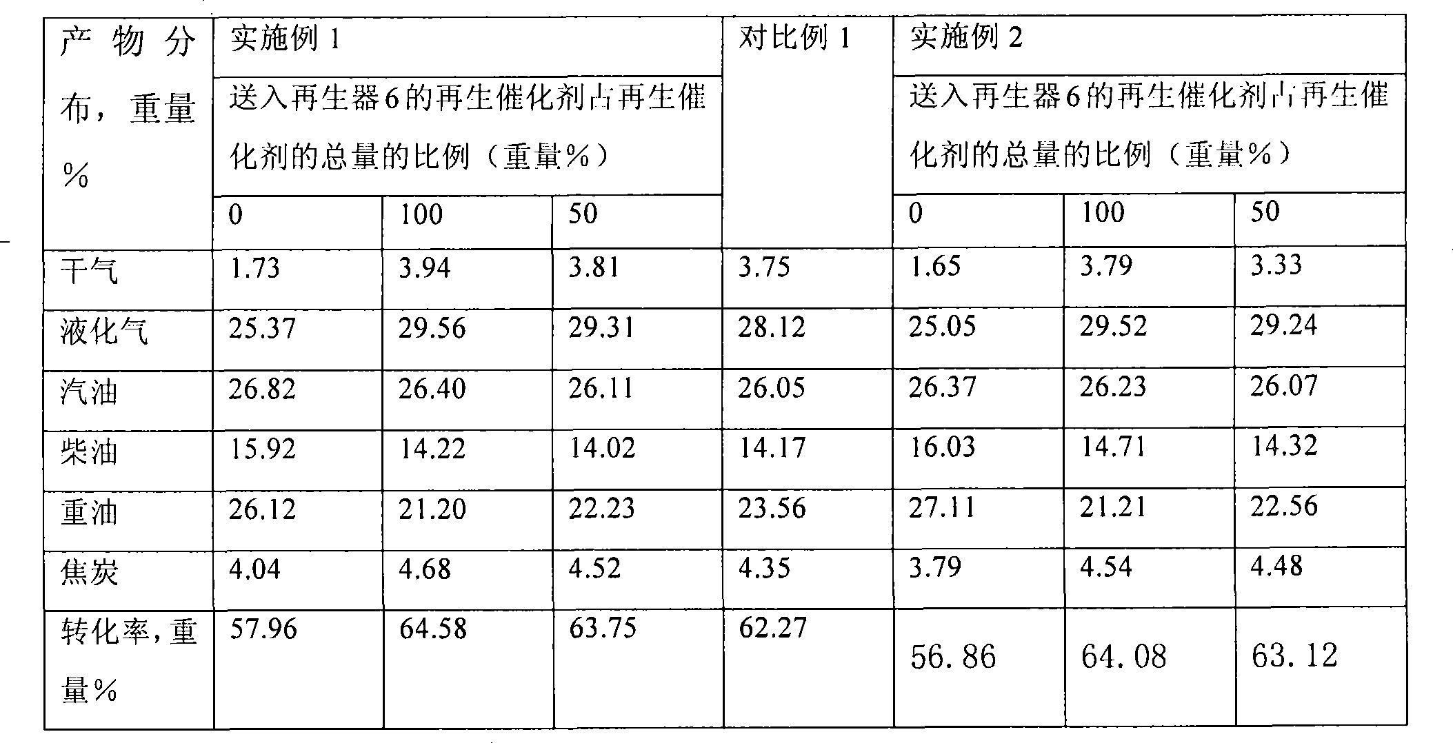
[0040] The hydrocarbon oil was converted in the same manner as in Example 1, except that the reaction temperature in the gasifier was 660°C. The composition of the synthesis gas is shown in Table 3. The product distribution of the reaction products in riser reactor 1 is shown in Table 4.

[0041] Table 1

[0042] Chemical composition, wt%

al 2 o 3

Na 2 o

Fe 2 o 3

50.0

0.12

0.25 physical properties

Specific surface, m 2 / g

Pore ​​volume, ml / g

Bulk density, g / cm 3

116

0.172

0.80 Metal content, m%

Ni

V

Fe

Ca

Na

Sb

0.62

0.29

0.27

0.056

0.44

0.23 Sieve, volume %

0-20μm

0-40μm

0-80μm

0-110μm

0-149μm

Average particle size, μm

0.4

9.7

56.4

77.8

93.5

74.4

[0043] Table 2

[0044] Density (20℃...


PUM


Abstract

The present invention discloses a hydrocarbon oil convert method, wherein the method includes the following procedures: under cracking condition, contact hydrocarbon oil with energizing agent in a reactor to obtain reaction product and spent catalyst; separate the reaction product and spent catalyst, and contact the spent catalyst with water vapor and oxygen-containing gas inside a gasifying stove to obtain forming gas and semi-regenerated catalyst; separate the forming gas with the semi-regenerated catalyst, and transmit at least part of the semi-regenerated catalyst into the reactor for periodic duty, wherein reaction temperature inside the gasifying stove is from 500 DEG C to lower than 800 DEG C. The hydrocarbon oil convert method provided in the invention makes spent catalyst contactwith water vapor and oxygen-containing gas in the temperature from 500 DEG C to lower than 800 DEG C, and that can increase production quantity of carbon monooxide and hydrogen; carbon monooxide can be converted to hydrogen in the following course of working to obtain higher hydrogen rate of production; the energizing agent that regenerated in the temperature from 500 DEG C can improve hydrogen rate of production and improve product distribution of hydrocarbon oil reaction product.

Description

technical field [0001] The invention relates to a hydrocarbon oil conversion method. Background technique [0002] Catalytic cracking is one of the important means of petroleum secondary processing, which is used to produce gasoline, diesel, liquefied petroleum gas, etc. from heavy hydrocarbon oil. Generally speaking, the hydrocarbon oil cracking method includes contacting the hydrocarbon oil with a catalyst in a reactor under cracking conditions, and the hydrocarbon oil generates cracked products (the cracked products include light oil and gas) through a cracking reaction under the action of the catalyst. At the same time, the coke generated by the reaction is deposited on the catalyst, and the catalyst deposited with coke is generally called the spent catalyst; the spent catalyst and the cracked product are separated in the reaction settler, and the spent catalyst enters the reaction stripper to remove the carried oil gas After entering the regenerator for regeneration, t...

Claims


Application Information

Patent Timeline
Patent Type & Authority Applications(China)
IPC IPC(8): C10G11/00C10G11/18C01B3/26
CPCY02P20/584
Inventor 龙军吴治国汪燮卿张久顺毛安国谢朝钢
Owner CHINA PETROLEUM & CHEM CORP
Why Eureka
Try Eureka