
Two-locking bridge type stonecutter

A stone cutting machine, double locking technology, applied in the direction of stone processing tools, stone processing equipment, work accessories, etc., can solve the problems of easy damage of diamond cutter heads, increase time and cost, affect the quality of work, etc. Long life and good rigidity

Active Publication Date: 2011-11-09
福建省晋江市和盛机械有限公司
View PDF0 Cites 1 Cited by
  • Summary
  • Abstract
  • Description
  • Claims
  • Application Information

AI Technical Summary

Problems solved by technology

[0002] At present, the four guide pillar bridge stone cutters used in stone processing, because there is no dustproof device, the hard stone dust in the air will inevitably cause wear and tear at the sliding joint between the guide post and the body, and the gap between the joints will increase with the use of the machine. The increase of the corresponding machine is getting bigger and bigger, and the shaking of the guide column is getting bigger and bigger when the corresponding machine is working. At the same time, the tooth side clearance between the two ends of the girder and the gears and racks of the left and right guide girders also leads to the girder and the gear installed on the girder. The working parts on the saw vibrate during operation, and the above-mentioned sloshing produces irregular additional force, which acts on the saw blade. Time and cost, the second is that the diamond cutter head on the saw blade is easily damaged, the machine wears quickly, and the service life is only 2 to 3 years; The lengthening of the machine will reduce the accuracy and affect the quality of work; in addition, the sliding joints of the body must be lubricated 3 to 5 times a day, resulting in high maintenance costs and low output.

Method used


Image

  • Two-locking bridge type stonecutter
  • Two-locking bridge type stonecutter
  • Two-locking bridge type stonecutter

Examples


Embodiment 1

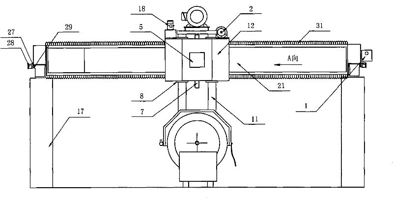
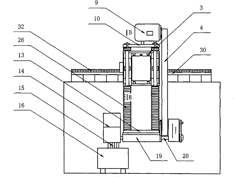
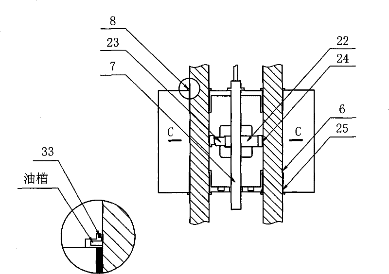
[0027] Such as figure 1 , 2 , 3, 4, 5, and 6 shown in double-locking bridge-type stone cutter, including machine pier 17, guide beam 30, girder 21, transmission device 1, 2, 4, hydraulic device 18, working parts, wherein the working parts It includes a body 12, a guide post 11, and a saw blade 15. Its structural features are: the stone cutter is equipped with a double locking device, and four sets of self-lubricating bearings 25 are installed in the body 12, and each set of self-lubricating bearings 25 is connected with a The guide post 11 is slidingly fitted, the self-lubricating bearing 25 and the guide post 11 are fitted with a combined double sealing device, the linear guide rail 3, the guide beam 30 and the girder are installed between the body 12 and the girder 21 passing through the body 12 21 is provided with a dust cover.

[0028]The double locking device is composed of a guide post hydraulic locking device and a girder hydraulic locking device, the guide post hydra...

Embodiment 2

[0035] Such as figure 1 , 2 , 3, 7, 8, 9 shown in the double locking bridge stone cutter, the double locking device is composed of the guide post cam locking device and the girder cam locking device, the guide post cam locking device is installed in the machine body, The girder cam locking device is installed at both ends of the girder. The guide post cam locking device is composed of a guide post locking cam 34, a guide post return spring 35, a guide post locking plate 22 and a guide post friction plate 24. The guide post friction plate 24 is fixed on the guide post locking plate 22, and the guide post locking plate 22 leans against the guide post locking cam 34; The girder friction plate 29 is composed of the girder friction plate 29 fixed on the girder locking plate 27, and the girder locking plate 27 leans against the girder locking cam 36; when the machine is in operation, the cam rotates at a certain angle to push the locking plate and the friction plate respectively I...


PUM


Abstract

The invention relates to a double locking bridge type stone cutting machine, which comprises a machine block, a guide beam, a crossbeam, a transmission device, a hydraulic device and a working component, wherein the working component comprises a machine body, guide posts and a saw blade. The structure of the stone cutting machine is characterized in that the stone cutting machine is provided witha double locking device; four sets of self-lubricating bearings are arranged in the machine body and each set of bearings are slidably matched with one guide post; the matching part of the self-lubricating bearings and the guide posts is provided with a combination type double sealing device; and a linear guide rail is arranged between the machine body and the crossbeam and dust proof covers are arranged on the machine body and the crossbeam. Stones processed by the machine have high precision and compared with the prior machines, and the machine improves the output by 10 percent to 12 percent. Therefore, the use cost is reduced and the service life of the machine is prolonged by one time.

Description

technical field [0001] The invention relates to a building material and stone processing machine, in particular to a double-locking bridge stone cutter. Background technique [0002] At present, the four guide pillar bridge stone cutters used in stone processing, because there is no dustproof device, the hard stone dust in the air will inevitably cause wear and tear at the sliding joint between the guide post and the body, and the gap between the joints will increase with the use of the machine. The increase of the corresponding machine is getting bigger and bigger, and the shaking of the guide column is getting bigger and bigger when the corresponding machine is working. At the same time, the tooth side clearance between the two ends of the girder and the gears and racks of the left and right guide girders also leads to the girder and the gear installed on the girder. The working parts on the saw vibrate during operation, and the above-mentioned sloshing produces irregular ...

Claims


Application Information

Patent Timeline
Patent Type & Authority Patents(China)
IPC IPC(8): B28D1/02B28D7/02
Inventor 苏友谊
Owner 福建省晋江市和盛机械有限公司
Learn More