
Special free-forging hydraulic unit and use method thereof

A hydraulic unit, free technology, applied in forging presses, forging presses, driving devices of forging presses, etc., can solve the problems of large vibration, low product dimensional accuracy, large equipment investment, etc., to reduce height and width, reduce equipment weight , the effect of reducing investment costs

Active Publication Date: 2009-06-17
MCC CAPITAL ENGINEERING & RESEARCH
View PDF0 Cites 14 Cited by
  • Summary
  • Abstract
  • Description
  • Claims
  • Application Information

AI Technical Summary

Problems solved by technology

[0003] Steam-air dual-purpose free forging hammer, air hammer, and electro-hydraulic hammer have large vibration during production and low product dimensional accuracy; free forging hydraulic presses and rapid free forging hydraulic presses are general free forging equipment, if used for professional production of shafts that do not require upsetting technology Forging products, the production capacity of the equipment cannot be utilized, which relatively increases the production cost; although mechanical or hydraulic precision forging machines are suitable for the production of shaft forgings, the equipment investment is very large
[0004] It can be seen that the above-mentioned existing forging equipment obviously still has inconvenience and defects in structure, method and use, and needs to be further improved urgently.
In order to solve the problems existing in the existing forging equipment, the relevant manufacturers have tried their best to find a solution, but for a long time no suitable design has been developed, and there is no suitable structure for general products to solve the above problems. This is obviously a problem that relevant industry players are eager to solve

Method used


Image

  • Special free-forging hydraulic unit and use method thereof
  • Special free-forging hydraulic unit and use method thereof
  • Special free-forging hydraulic unit and use method thereof

Examples


Embodiment Construction

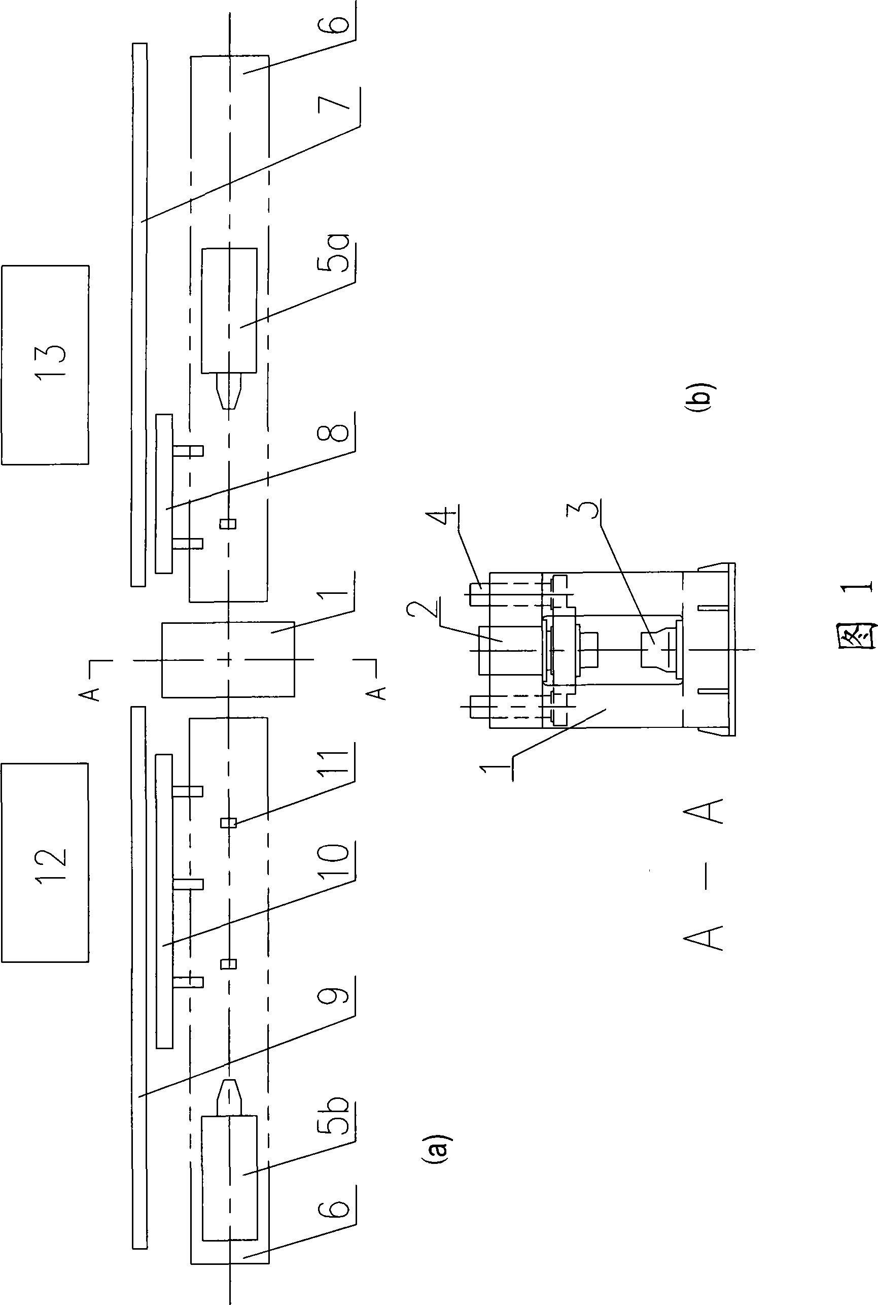
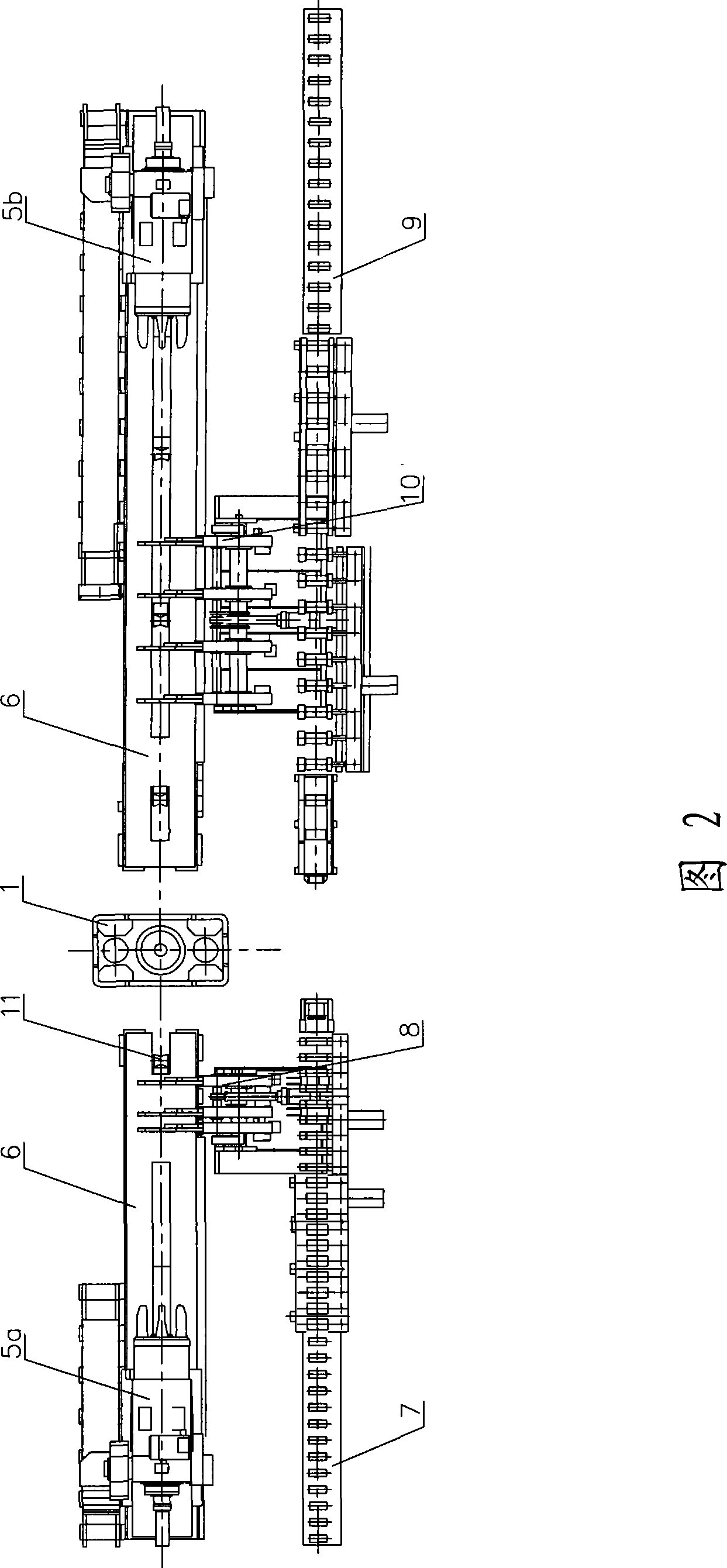
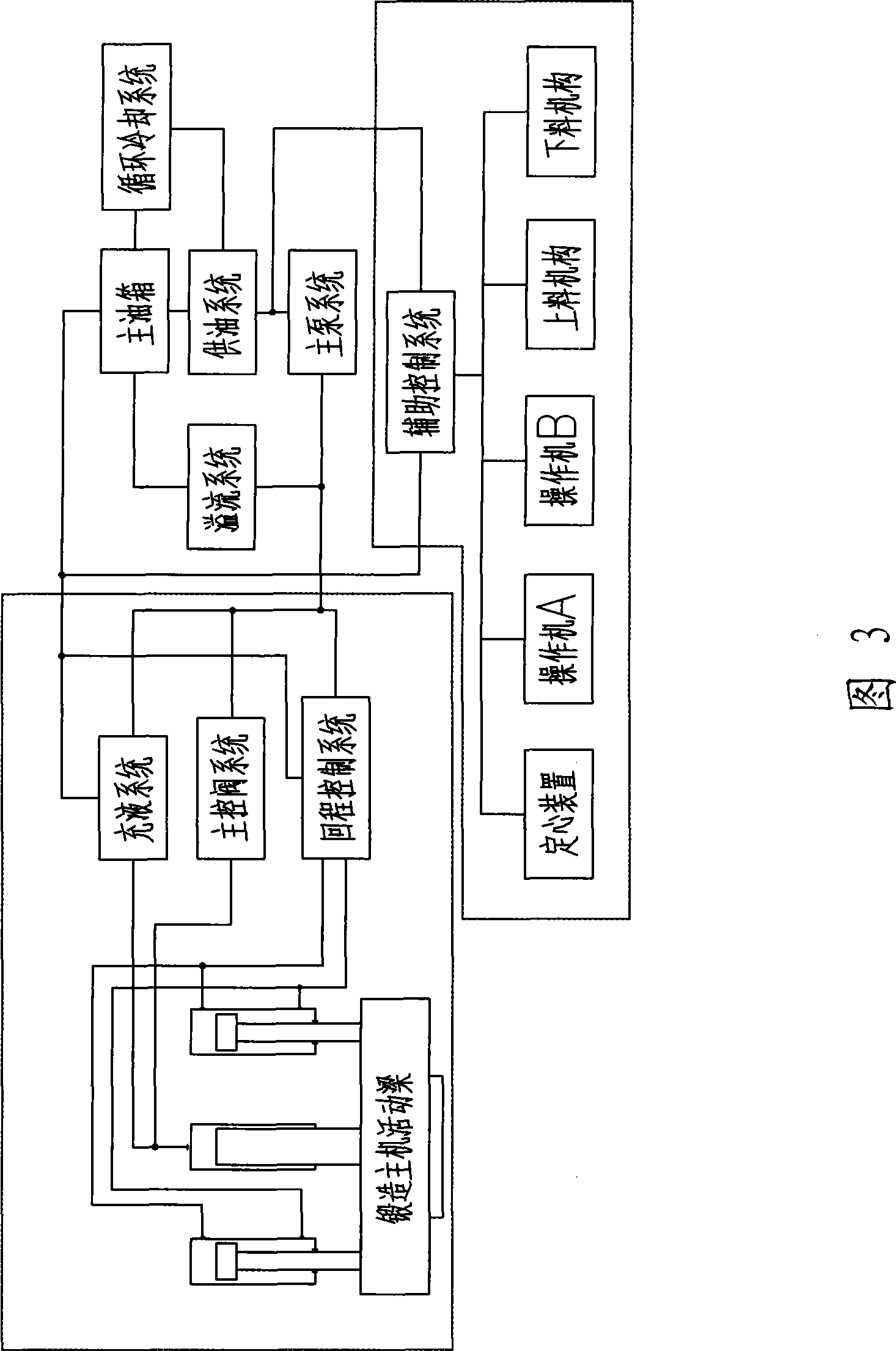
[0053] In order to further explain the technical means and effects of the present invention to achieve the intended purpose of the invention, the specific implementation and structure of the special free forging hydraulic unit and its use method proposed according to the present invention will be described below in conjunction with the accompanying drawings and preferred embodiments. , method of use, steps, features and effects thereof are detailed as follows.

[0054] The present invention adopts the design parameters of the main forging machine that is compatible with the product specifications of forging shafts, and uses a pair of forging anvils to reduce the size and weight of the forging main machine mechanical equipment compared with the general free forging hydraulic press equipment; The adaptable and compact structural layout of the equipment can realize automatic operation and constitute a special free forging hydraulic unit.

[0055] The specifications of the forging...


PUM


Abstract

The invention relates to a special free forging hydraulic unit and a use method thereof. The special free forging hydraulic unit comprises a mechanical device of a main forging machine, a mechanical device of an assistant system, a hydraulic drive system for the main machine and the assistant system, and an electric automatic control device, wherein the mechanical device of the main forging machine comprises a main sealing frame, a work oil cylinder, a forging anvil mechanical assembly and a return cylinder mechanical assembly; and the mechanical device of the assistant system comprises a forging mechanical manipulator, a forging mechanical manipulator, a manipulator walk under carriage, a guide rail, a feeding roller way, a feeding manipulator, a discharging roller way, a discharging manipulator and an automatic centering mechanism. The special free forging hydraulic unit can adopt a hybrid operation mode combining a manual mode and a full automatic mode, not only can satisfy the requirement of product production and achieve production efficiency higher than a general free forging hydraulic press, but also effectively reduces investment cost of the devices.

Description

technical field [0001] The invention relates to a special complete set of equipment suitable for the production of small and medium-sized metal thermal processing shaft forging products, in particular to a special free forging hydraulic unit including a forging main engine directly driven by hydraulic pressure and auxiliary systems of electromechanical and hydraulic transmission and how to use it. Background technique [0002] At present, the production of small and medium-sized metal thermal processing shaft forging products usually uses steam-air dual-purpose free forging hammer, air hammer, electro-hydraulic hammer, free forging hydraulic press, fast free forging hydraulic press, precision forging machine-mechanical or hydraulic style. [0003] Steam-air dual-purpose free forging hammer, air hammer, and electro-hydraulic hammer have large vibration during production and low product dimensional accuracy; free forging hydraulic presses and rapid free forging hydraulic pres...

Claims


Application Information

Patent Timeline
IPC IPC(8): B21J9/00B21J13/10B21J9/12B21J9/18B21K27/00
Inventor 林怀峰李占云戴哲王燕红王震黄木
Owner MCC CAPITAL ENGINEERING & RESEARCH
Learn More