Microchannel for separating blood plasma
A plasma separation and micro-channel technology, which is applied in the field of flow channel structure of blood cells and plasma, can solve problems such as difficult separation of blood, and achieve the effect of simple plasma separation
- Summary
- Abstract
- Description
- Claims
- Application Information
AI Technical Summary
Problems solved by technology
Method used
Image
Examples
Embodiment 1
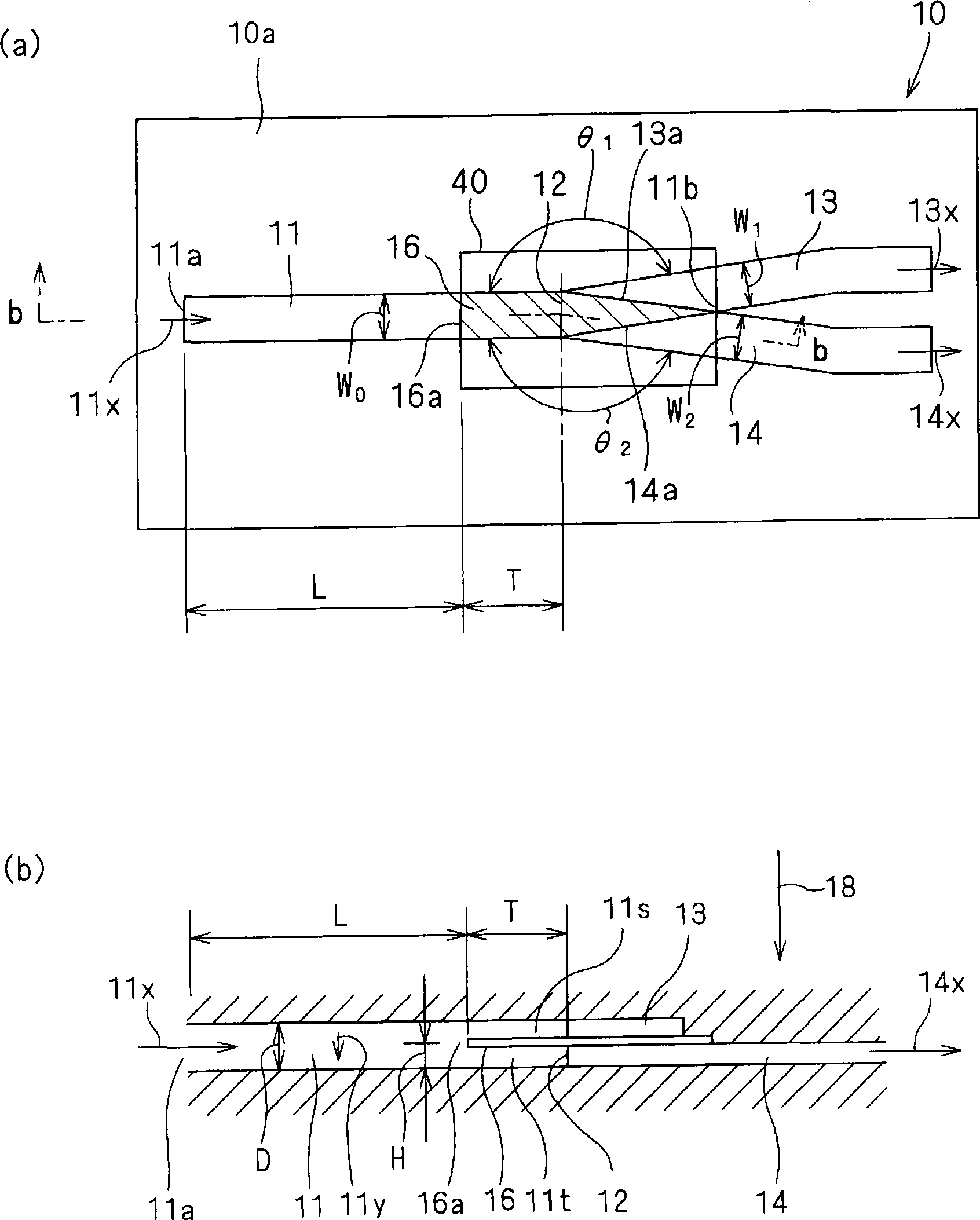
[0051] use Figure 1 ~ Figure 4 A microchip for blood testing (hereinafter also simply referred to as "microchip") according to Example 1 of the present invention will be described.
[0052] refer to figure 1 The basic structure of the microchip 10 will be described. figure 1 (a) is a top perspective view, figure 1 (b) is along figure 1 The sectional view cut off by b-b in (a).
[0053] Such as figure 1 As shown in (a), the microchip 10 has flow paths 11 , 13 , and 14 formed in a substantially Y shape substantially parallel to the extending direction of the substrate body 10 a inside the substrate body 10 a serving as the main body of the microchip 10 . That is, on the side of the one end 11b of the separation flow path 11, the first branch flow path 13 and the second branch flow path are branched from the communication ports 13a, 14a formed adjacently in the thickness direction perpendicular to the direction in which the substrate body 10a extends. 14.
[0054] A ...
Embodiment 2
[0094] use Figure 5 ~ Figure 8 The microchip for blood tests (hereinafter also simply referred to as "microchip") 100 of Example 2 will be described.
[0095] The microchip 100 of the second embodiment has substantially the same configuration as the microchip 10 of the first embodiment. Figure 5 It is (a) top perspective view, (b) side perspective view of the microchip 100. FIG. Figure 6 It is (a) plan view and (b) side view of upper substrate 130 . Figure 7 It is (a) plan view and (b) side view of the lower substrate 120 .
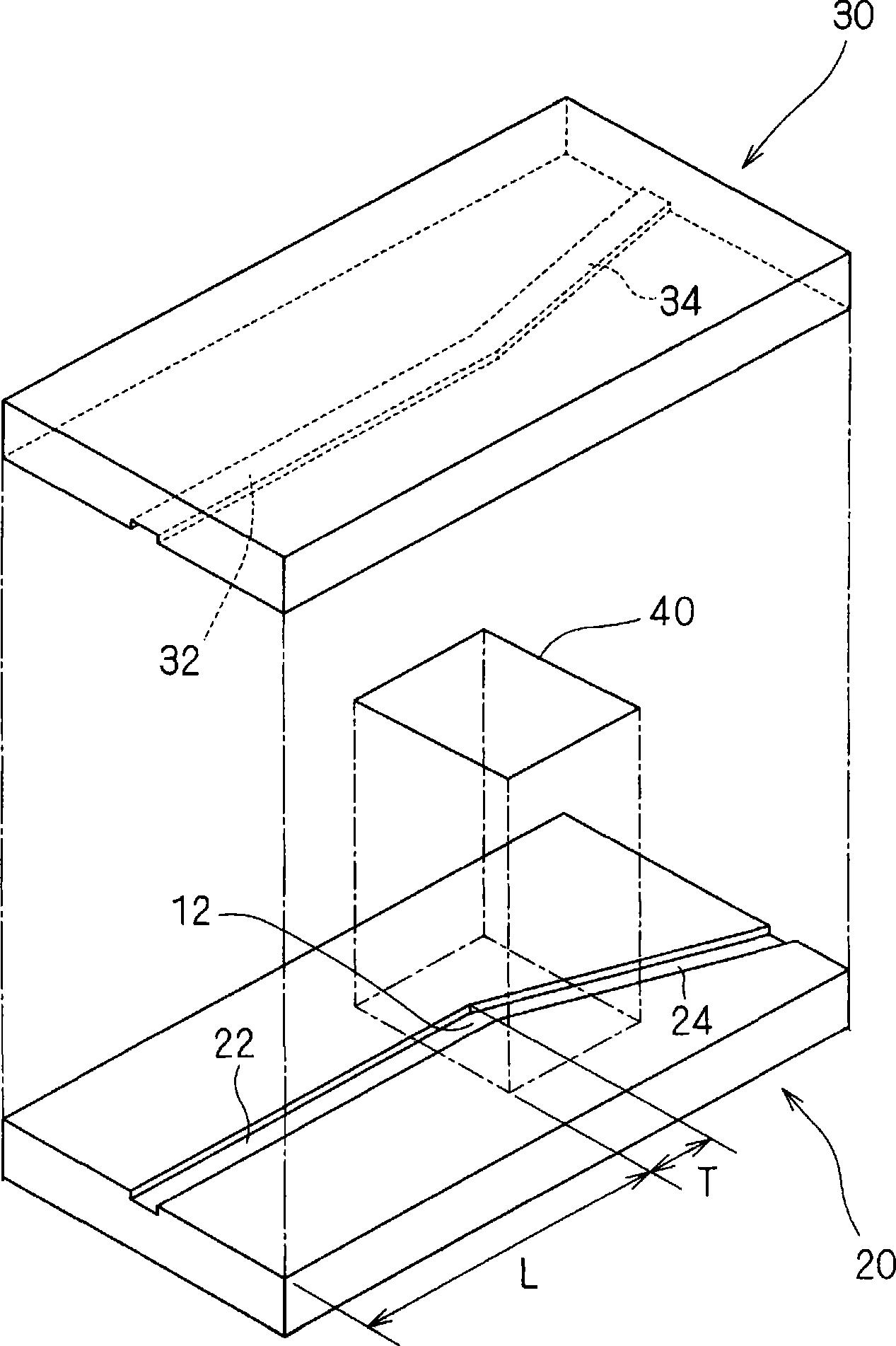
[0096] Such as Figure 5 ~ Figure 7 As shown, the microchip 100 is the same as in Example 1. A thin plate 140 for forming a partition structure is sandwiched between substrates 120, 130 formed with grooves 122, 124 and grooves 132, 134 as Y-shaped flow paths, and separated. The flow path 110 is branched into a first branch flow path 113 and a second branch flow path 114 .
[0097] Unlike Example 1, the groove 134 serving as the separation channel...
Embodiment 3
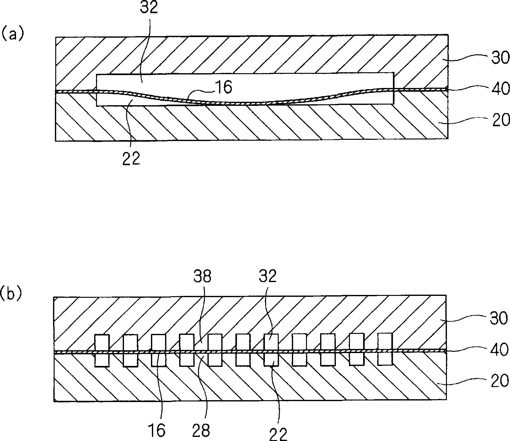
[0110] refer to Figure 9 ~ Figure 11The microchip array for blood tests (hereinafter also simply referred to as "microchip array") 200 of Example 3 will be described. Figure 9 is a top perspective view of microchip array 200 . Figure 10 is along Figure 9 A cross-sectional view cut from A-A in . Figure 11 is along Figure 9 The cut-off view of B-B in .
[0111] The microchip array 200 of the third embodiment has the same configuration as that of the first and second embodiments. Hereinafter, differences from Embodiment 1 and Embodiment 2 will be mainly described.
[0112] Such as Figure 9 ~ Figure 11 As shown, in the microchip array 200 , two sets of flow path structures 220 are formed on a substrate body 210 formed by bonding a pair of substrates 212 and 214 with parallel planes. For example, glass substrates are used in the substrates 212 and 214, and CH 3 The flow path structure 220 is formed by plasma etching or ion beam etching with a fluorine-based gas such ...
PUM
| Property | Measurement | Unit |
|---|---|---|
| Thickness | aaaaa | aaaaa |
Abstract
Description
Claims
Application Information
 - R&D Engineer
- R&D Manager
- IP Professional
- Industry Leading Data Capabilities
- Powerful AI technology
- Patent DNA Extraction
Browse by: Latest US Patents, China's latest patents, Technical Efficacy Thesaurus, Application Domain, Technology Topic, Popular Technical Reports.
© 2024 PatSnap. All rights reserved.Legal|Privacy policy|Modern Slavery Act Transparency Statement|Sitemap|About US| Contact US: help@patsnap.com


