
Electro-acoustic conversion device and diaphragm thereof

A technology of electroacoustic conversion and electric energy, applied in the direction of electrical components, sensors, etc., can solve the problems of general products without structure, inconvenience, unfavorable production, etc.

Inactive Publication Date: 2009-06-10
MERRY ELECTRONICS CO LTD
View PDF0 Cites 4 Cited by
  • Summary
  • Abstract
  • Description
  • Claims
  • Application Information

AI Technical Summary

Problems solved by technology

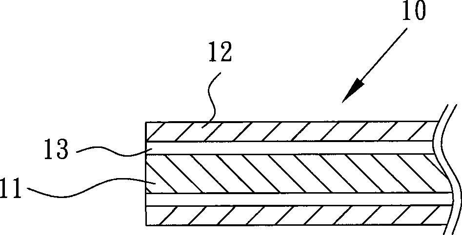
[0005] Since the volume of the diaphragm used in the microphone or loudspeaker is not too large, following the above-mentioned production process, after the aluminum sheet 12 is glued to the foam 11, it is necessary to wait until the adhesive 13 is dry. It can be cut, but in this way, the manufacturing of the diaphragm 10 must go through complicated procedures such as material preparation, gluing, rolling, drying, and cutting, especially in the waiting time for drying. The above-mentioned lack of existing diaphragm and its manufacturing method really have the need to be improved as soon as possible
[0006] It can be seen that the above-mentioned existing electroacoustic conversion device and its vibrating membrane obviously still have inconvenience and defects in structure and use, and need to be further improved urgently.
In order to solve the above-mentioned problems, the relevant manufacturers have tried their best to find a solution, but for a long time no suitable design has been developed, and the general products do not have a suitable structure to solve the above-mentioned problems. This is obviously related The problem that the industry is eager to solve

Method used


Image

  • Electro-acoustic conversion device and diaphragm thereof
  • Electro-acoustic conversion device and diaphragm thereof
  • Electro-acoustic conversion device and diaphragm thereof

Examples


Embodiment Construction

[0044] In order to further explain the technical means and effects adopted by the present invention to achieve the intended purpose of the invention, below in conjunction with the accompanying drawings and preferred embodiments, the specific implementation, structure, Features and their functions are described in detail below.

[0045]The aforementioned and other technical contents, features and effects of the present invention will be clearly presented in the following detailed description of preferred embodiments with reference to the drawings. Through the description of the specific implementation mode, when the technical means and functions adopted by the present invention to achieve the predetermined purpose can be obtained a deeper and more specific understanding, but the accompanying drawings are only for reference and description, and are not used to explain the present invention be restricted.

[0046] A diaphragm and its manufacturing method according to preferred e...


PUM


Abstract

The invention provides an electroacoustic conversion device and a vibrating diaphragm. The electroacoustic conversion device comprises a shell, a magnetic loop device, a sound coil and a vibrating diaphragm, wherein the magnetic loop device is arranged in the shell and can generate a magnetic loop; the sound coil is arranged on a route of the magnetic loop and can receive electric energy to generate magnetism; and the vibrating diaphragm is fixedly arranged in the sound coil and made of metal material, and the cross section of the vibrating diaphragm is continuous concave-convex-shaped. When the sound coil of the electroacoustic conversion device generates the magnetism by the electric energy, by the interaction of the sound coil and the magnetic loop, the vibrating diaphragm is caused to vibrate to make a sound. The vibrating diaphragm is arranged in the electroacoustic conversion device and made of metal material, and the cross section of the vibrating diaphragm is continuous concave-convex-shaped. The vibrating diaphragm is directly processed only by a metal plate, thereby saving conventional foam material and further reducing flow; moreover, due to the arrangement of the concave-convex pattern, the vibrating diaphragm can withstand bigger stress and is easily developed toward thinness, and when the vibrating diaphragm is used in the electroacoustic conversion device, the space occupied by the vibrating diaphragm is reduced.

Description

technical field [0001] The invention relates to an electroacoustic conversion device and its diaphragm, in particular to an electroacoustic conversion device and its diaphragm which is easy to manufacture and can reduce manufacturing procedures and production time. Background technique [0002] At present, the more common electroacoustic conversion devices, such as microphones or speakers, are generally equipped with a diaphragm inside. When used in a microphone, the diaphragm vibrates it through sound waves, changing the change of the magnetic field in the microphone and generating The corresponding electronic signal is received and processed by the control device electrically connected with it. In addition, when it is applied to a speaker, the control device transmits the processed electronic signal to the speaker to change the change of the magnetic field in the speaker, and then drives the diaphragm to vibrate, thereby emitting sound waves. [0003] see figure 1 Shown ...

Claims


Application Information

Patent Timeline
IPC IPC(8): H04R9/02H04R9/06
Inventor 张瑞成
Owner MERRY ELECTRONICS CO LTD
Learn More