Direct combustion furnace
A direct-fired furnace and furnace body technology, which is applied to household furnaces/stoves, solid heating fuels, furnaces/stoves with hot water devices, etc. It can solve problems such as high thermal efficiency, pollute the environment, and waste energy to avoid pollution , save energy, prevent environmental pollution
- Summary
- Abstract
- Description
- Claims
- Application Information
AI Technical Summary
Problems solved by technology
Method used
Image

Examples
specific Embodiment approach 1
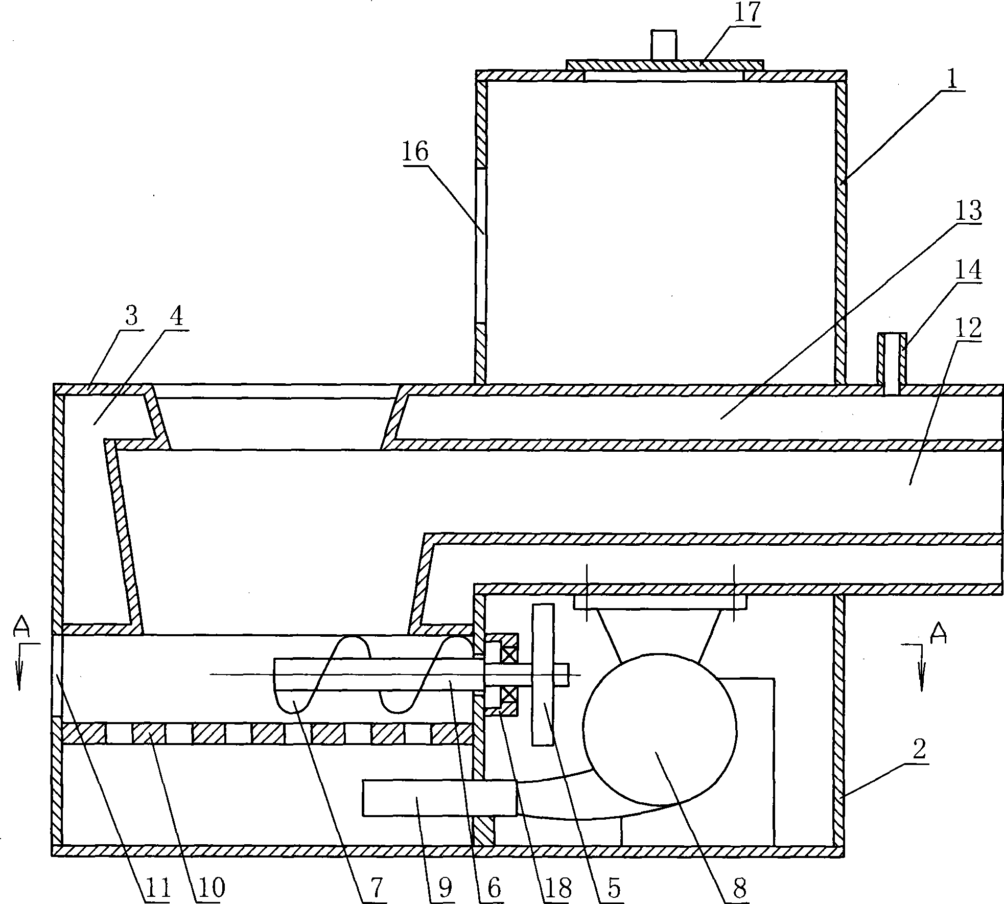
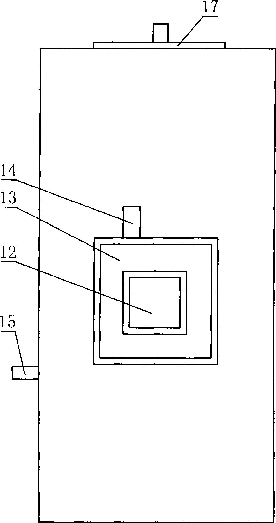
[0013] Specific implementation mode one: combine Figure 1 ~ Figure 4 Describe this embodiment, present embodiment is made up of feeding box 1, feeding box 2 and body of heater 3, upper material box 1, feeding box 2 and body of heater 3 are made into one, body of heater 3 top has water tank 4, body of heater 3 A furnace cover is provided at the furnace mouth, a furnace wall 10 is provided in the inner cavity of the furnace body 3, a feeding port 13 is provided on the top of the feeding box 1, a feeding cover 17 is provided on the feeding port 13, and a driving device is provided in the feeding box 2 5. The driving device 5 is connected with the screw shaft 6, one end of the screw shaft 6 is hinged on the bracket 18, the other end is set above the furnace wall 10, the bracket 18 is fixed on the feeding box 2, and the screw shaft 6 is provided with a screw piece 7 , the feeding box 2 is provided with a blower fan 8, the blower fan 8 is fixed on the top of the feeding box 2 inner...
specific Embodiment approach 2
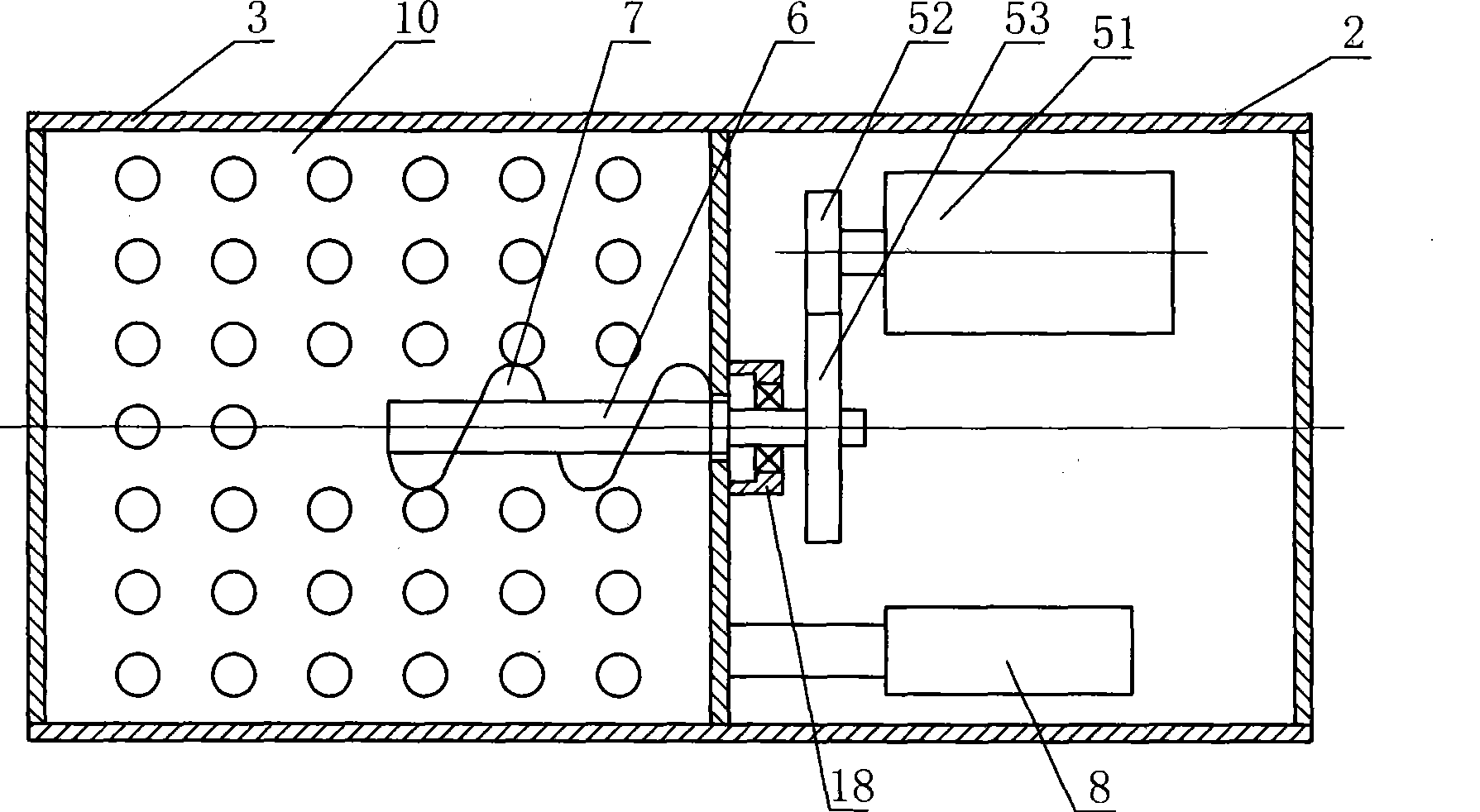
[0014] Specific implementation mode two: combination figure 1 and figure 2 Illustrate this embodiment, the driving device 5 of this embodiment comprises motor 51, and motor 51 is arranged on the bottom of feeding box 2 inner cavity, and driving wheel 52 is housed on the output shaft of motor 51, and driving wheel 52 meshes with driven wheel 53, and driven wheel 53 Installed on the screw shaft 6. This design makes the screw shaft 6 rotate slowly, the material conveyed by the screw blade 7 is relatively uniform, and the combustion effect is good.
specific Embodiment approach 3
[0015] Specific implementation mode three: combination figure 1 and Figure 4 The difference between this embodiment and the first embodiment is that this embodiment also adds a material viewing port 1-1, and the material viewing port 1-1 is arranged on the front of the feeding box 1. Such arrangement can make it possible to observe the quantity of material in the feeding box 1 at any time. Other compositions and connections are the same as in the first embodiment.
[0016] The working process of the present invention is briefly described as follows:
[0017] For the above-mentioned direct-fired furnace, see Figure 1 ~ Figure 4 First, the rice husk is poured from the feeding port 13, and the rice husk falls on the spiral sheet 7, ignites the rice husk on the spiral sheet 7, drives the motor 51, drives the screw shaft 6 to rotate by the driving wheel 52 and the driven wheel 53, and the spiral sheet 7 also rotates thereupon, rice husk is constantly conveyed simultaneously, ...
PUM
 Abstract
Description
Claims
Application Information
 - R&D
- Intellectual Property
- Life Sciences
- Materials
- Tech Scout
- Unparalleled Data Quality
- Higher Quality Content
- 60% Fewer Hallucinations
Browse by: Latest US Patents, China's latest patents, Technical Efficacy Thesaurus, Application Domain, Technology Topic, Popular Technical Reports.
© 2025 PatSnap. All rights reserved.Legal|Privacy policy|Modern Slavery Act Transparency Statement|Sitemap|About US| Contact US: help@patsnap.com