
Method for manufacturing a machine felt and machine felt

一种机制、纵向纱线的技术,应用在造纸机、造纸、非织造布等方向,能够解决横向纱线作用有限、高制造成本等问题

Active Publication Date: 2009-06-10
HEIMBACH GMBH & CO KG
View PDF13 Cites 7 Cited by
  • Summary
  • Abstract
  • Description
  • Claims
  • Application Information

AI Technical Summary

Problems solved by technology

The effect of transverse threads is therefore limited, especially due to the high manufacturing costs due to the insertion process

Method used


Image

  • Method for manufacturing a machine felt and machine felt
  • Method for manufacturing a machine felt and machine felt
  • Method for manufacturing a machine felt and machine felt

Examples


Embodiment Construction

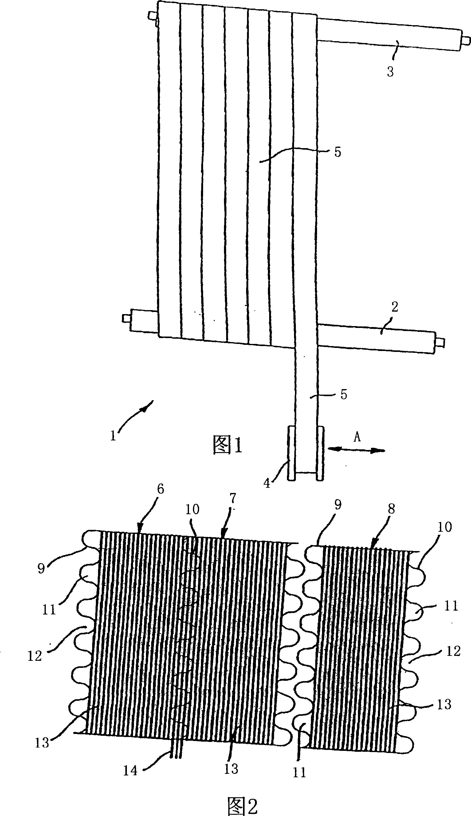
[0048] The device 1 shown in Figure 1 has two spaced apart rollers 2, 3 with parallel axes of rotation and driven in the same direction. The storage roller 4 is kept at a distance from the lower roller 2 , and the mesh belt 5 of synthetic material is wound on the storage roller 4 . When the rollers 2 , 3 are driven, the synthetic material mesh belt 5 is drawn off from the storage roller 4 and wound onto the two rollers 2 , 3 . In this case, the storage roller 4 moves in the direction of the arrow A, ie parallel to the axes of rotation of the rollers 2 , 3 . Thereby, the synthetic material mesh belt 5 is gradually wound to the right in a helical manner onto the rollers 2 , 3 . In this case, the feed of the storage rollers 4 in the direction of the arrow A is determined in such a way that the plastic mesh belts 5 abut each other with their adjacent edges. The accumulator rollers 4 are arranged at a corresponding inclination so that no skewing can occur. The winding process co...


PUM


Abstract

The invention relates to a machine felt and a method for manufacturing the same. Firstly a tube having a longitudinal yarn layer is manufactured with a peripheral length double the length of the machine felt, and a width that corresponds to the width of the machine felt. The tube is compressed into a flattened tube with the formation of longitudinal yarn loops which are exposed by the removal of fibers of a fiber batt layer. An auxiliary substrate web is manufactured with a width that is less than that of the machine felt; for the longitudinal yarns and / or for the auxiliary substrate web, a material is used that absorbs laser energy; the longitudinal yarns are brought together with the auxiliary substrate web and connected by a laser beam; the auxiliary substrate web is helically wound until the tube is formed; and upon exposure of the longitudinal yarn loops, the auxiliary substrate web(s) are also removed.

Description

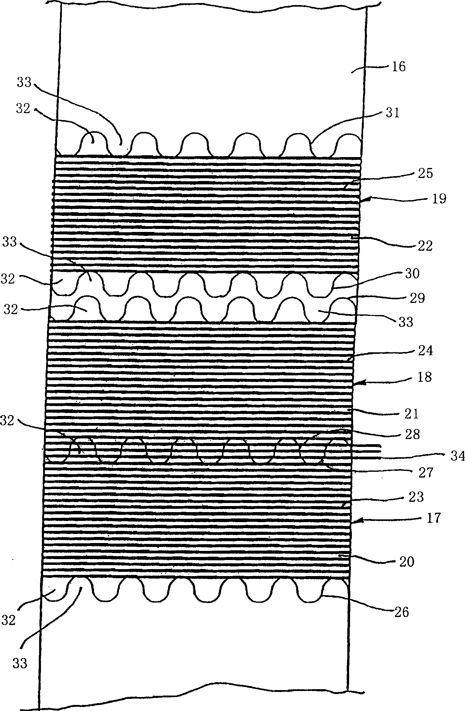
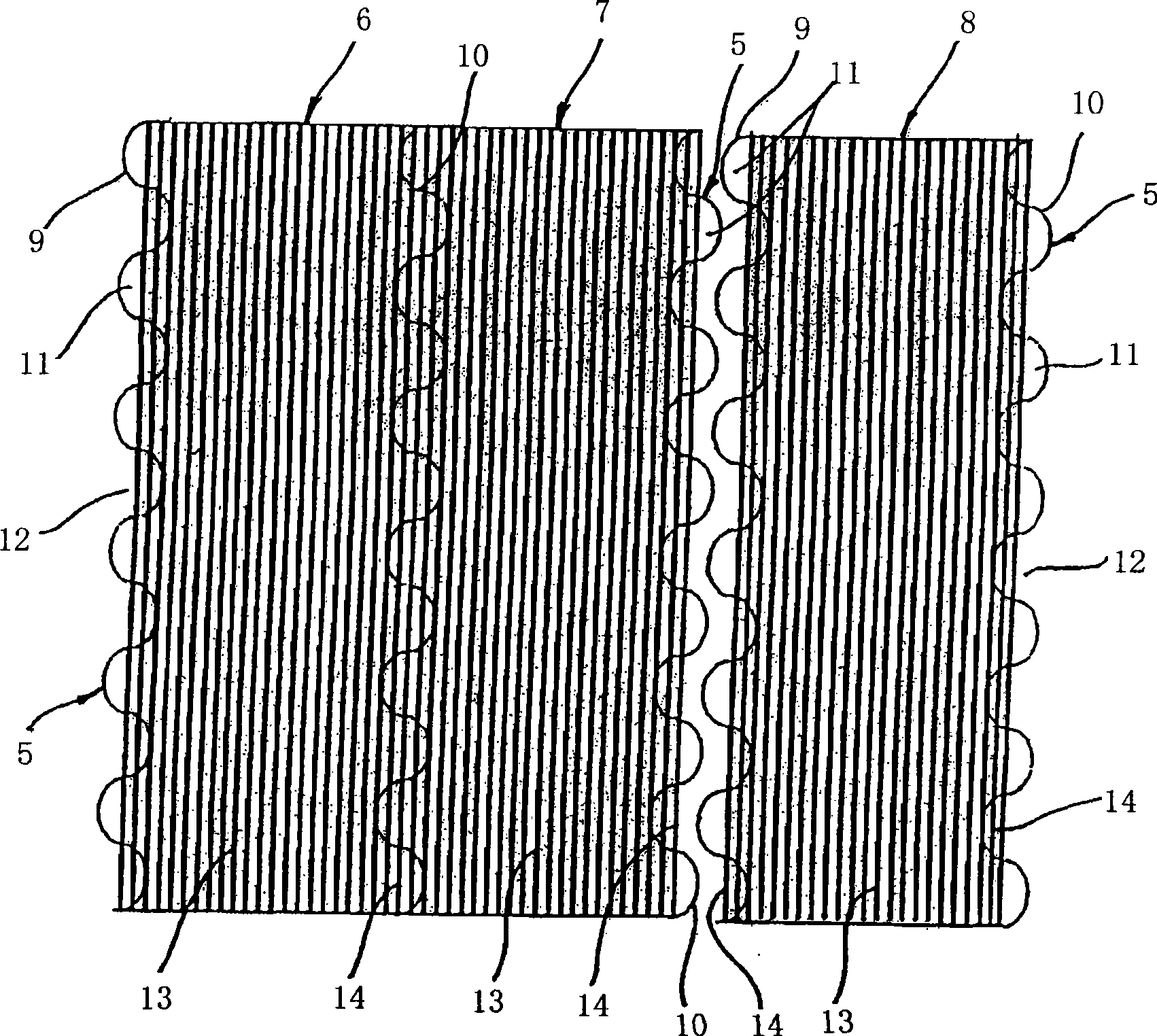
technical field [0001] The invention relates to a method for producing a machine-made felt of limited length, wherein first a tube is produced with a certain circumference and a certain width with at least one layer of longitudinal yarn linings, each of which is formed of parallel distributed longitudinal yarns, the circumference corresponds to at least twice the length of the machine-made felt to be produced, the width corresponds to at least the width of the machine-made felt to be produced, and wherein, subsequently, they are attached to each other inside the tube and forming the top edge and forming the longitudinal yarn loops at the top edge into a flat tube, the longitudinal yarn loops being formed by removing the fibers of the previously applied non-woven fabric layer, forming each Channels extending along the associated top edge are exposed. The invention also relates to a machine-made felt of limited length with a backing and a nonwoven layer fastened to the backing,...

Claims


Application Information

Patent Timeline
Patent Type & Authority Applications(China)
IPC IPC(8): D04H13/00D04H1/54D04H1/48D04H3/08D02G3/00B32B5/04
CPCB29C65/1616D21F7/083Y10S162/90Y10S162/904Y10T442/59
Inventor 瓦尔特·贝斯特阿克塞尔·博梅斯特克里斯蒂安·莫尔斯
Owner HEIMBACH GMBH & CO KG
Learn More