
Zero-order resonant antenna of compound transmission line based on left and right hands

A zero-order resonant antenna and left and right hand composite technology, applied in the field of zero-order resonant antenna, can solve the problems that it is difficult to meet the frequency bandwidth of transmitting/receiving signals at the same time, the narrow frequency band of the metal conductor sheet radiation unit, and the size limit of the microstrip antenna area, etc., to achieve Effects of low loss, size reduction, and miniaturization

Inactive Publication Date: 2009-06-03
INST OF MICROELECTRONICS CHINESE ACAD OF SCI
View PDF0 Cites 20 Cited by
  • Summary
  • Abstract
  • Description
  • Claims
  • Application Information

AI Technical Summary

Problems solved by technology

[0004] However, since the microstrip antenna works in a resonant mode, and its operating frequency is the resonant frequency, the length of the microstrip antenna patch is required to be half of the transmission wavelength, so that the area size of the microstrip antenna is limited by the operating frequency , also creates obstacles to the integration with MMIC; at the same time, due to the characteristics of the structure of the microstrip antenna itself, it is mainly manifested in the narrow frequency band of the radiating element of the metal conductor sheet, which makes its performance in bandwidth not as good as other types of antennas, and it is difficult to meet the requirements at the same time. The frequency bandwidth of the transmit / receive signal, and the transmit efficiency is low

Method used


Image

  • Zero-order resonant antenna of compound transmission line based on left and right hands
  • Zero-order resonant antenna of compound transmission line based on left and right hands
  • Zero-order resonant antenna of compound transmission line based on left and right hands

Examples


Embodiment Construction

[0018] In order to make the object, technical solution and advantages of the present invention clearer, the implementation manner of the present invention will be further described in detail below in conjunction with the accompanying drawings.

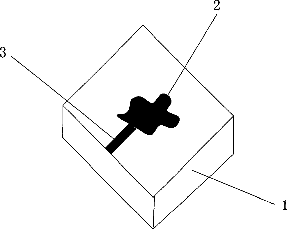
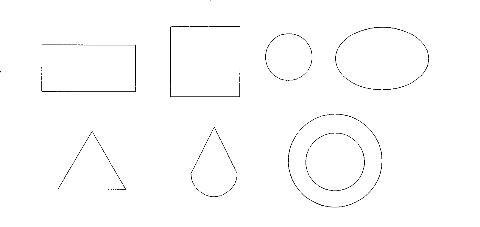
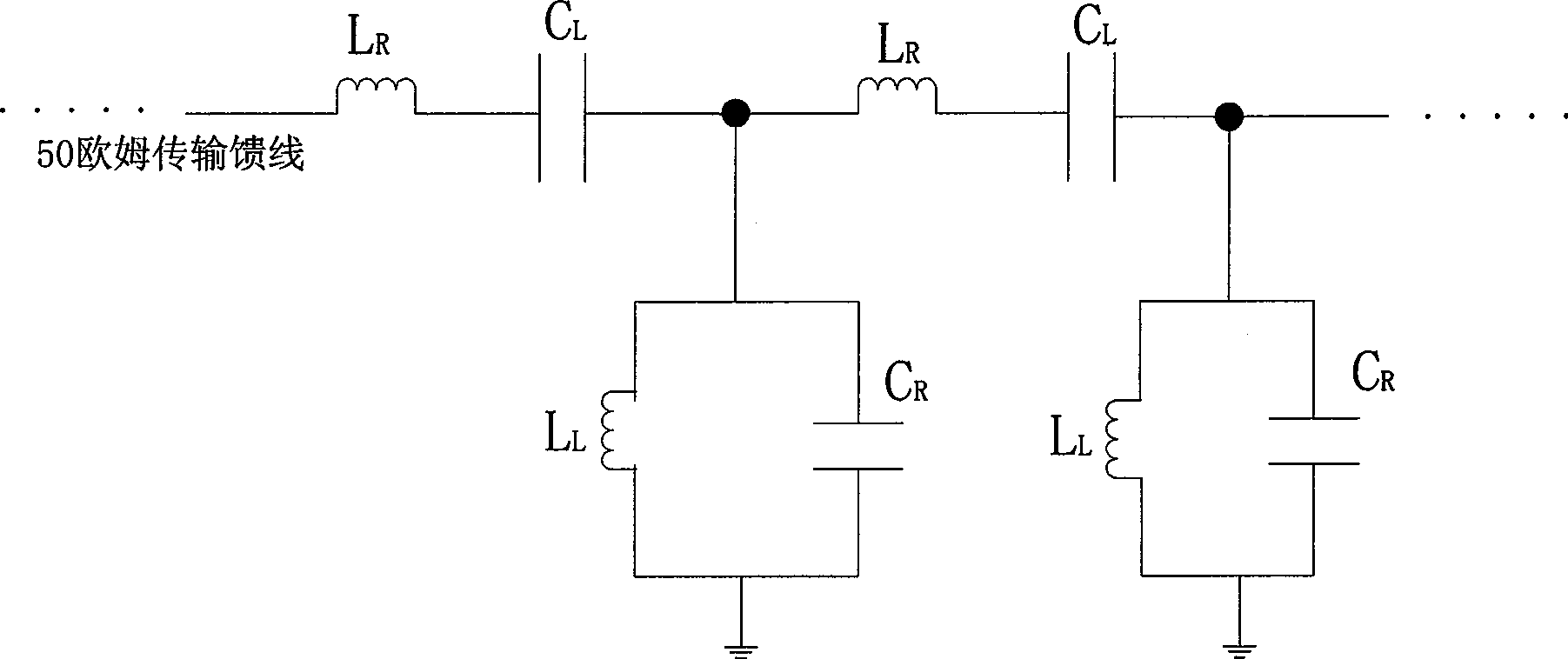
[0019] see image 3 , the embodiment of the present invention proposes a zero-order resonant antenna based on a left-handed composite transmission line, which is composed of a transmission feeder, a left-handed composite transmission line, and a dielectric substrate. The left and right hand composite transmission lines are connected to the dielectric substrate, and the transmission feeder is connected to the left and right hand composite transmission lines. Among them, the left-hand composite transmission line is composed of at least one transmission line unit in series; the transmission line unit is composed of the left-hand transmission line capacitance C L and the right hand transmission line inductance L R , and the parallel righ...


PUM

PropertyMeasurementUnit
Impedance valueaaaaaaaaaa

Abstract

The invention discloses a zero-order resonant antenna of a compound transmission line based on left and right hands. The zero-order resonant antenna belongs to the technical field of antenna, and comprises a transmission feed line, a left-right hand compound transmission line and a medium base, wherein, the left-right hand compound transmission line is connected with the medium base, and the transmission feed line is connected with the left-right hand compound transmission line; the left-right hand compound transmission line comprises at least one transmission line elements connected in series; and the transmission line elements comprise a left hand transmission line capacitance and a right hand transmission line inductance connected in series, and a right hand transmission line capacitance and a left hand transmission line inductance connected in parallel. The thin metallic conductor sheet on the traditional micro-strip antenna is replaced for the left-right hand compound transmission line so that the invention realizes the micro-strip antenna with high radiant efficiency and low loss; meanwhile, the radiation frequency of the zero-order resonant antenna is unrelated to the physical size of the transmission line elements; therefore, the size of the resonance type micro-strip antenna is greatly reduced so as to realize miniaturization of the antenna and facilitate integration of a microwave monolithic integration receiver system.

Description

technical field [0001] The invention relates to the technical field of antennas, in particular to a zero-order resonant antenna based on left-handed and left-handed composite transmission lines. Background technique [0002] In the past 50 years, microstrip antenna technology has become the fastest growing technology in the field of antenna technology, especially in the 1970s, with the development of microwave monolithic integrated circuit (Monolithic Microwave Integrated Circuit, MMIC) and various microwave low The emergence of lossy media makes microstrip antenna technology widely attract the attention of the global academic, industrial and government departments. In the field of microwave applications, microstrip antennas have rapidly evolved from an academic novelty to a commercial real product. With the rapid development of application markets such as personal communication systems, global positioning systems, direct broadcast satellites, wireless local area networks, ...

Claims


Application Information

Patent Timeline
IPC IPC(8): H01Q1/38H01Q13/08H01P3/00
Inventor 吴茹菲杨浩尹军舰张海英
Owner INST OF MICROELECTRONICS CHINESE ACAD OF SCI
Learn More