Liquid metal directional casting apparatus and process

A technology of directional casting and liquid metal, which is applied in casting molding equipment, metal processing equipment, casting molds, etc., and can solve problems such as damage to casting process reliability and molten metal pollution

Inactive Publication Date: 2009-05-27
GENERAL ELECTRIC CO
View PDF0 Cites 13 Cited by
  • Summary
  • Abstract
  • Description
  • Claims
  • Application Information

AI Technical Summary

Problems solved by technology

In addition, the molten metal will be contaminated by spilled cast metal
Therefore, if there is no effective sealing, the reliability of the casting process will be compromised

Method used


Image

  • Liquid metal directional casting apparatus and process
  • Liquid metal directional casting apparatus and process
  • Liquid metal directional casting apparatus and process

Examples


Embodiment Construction

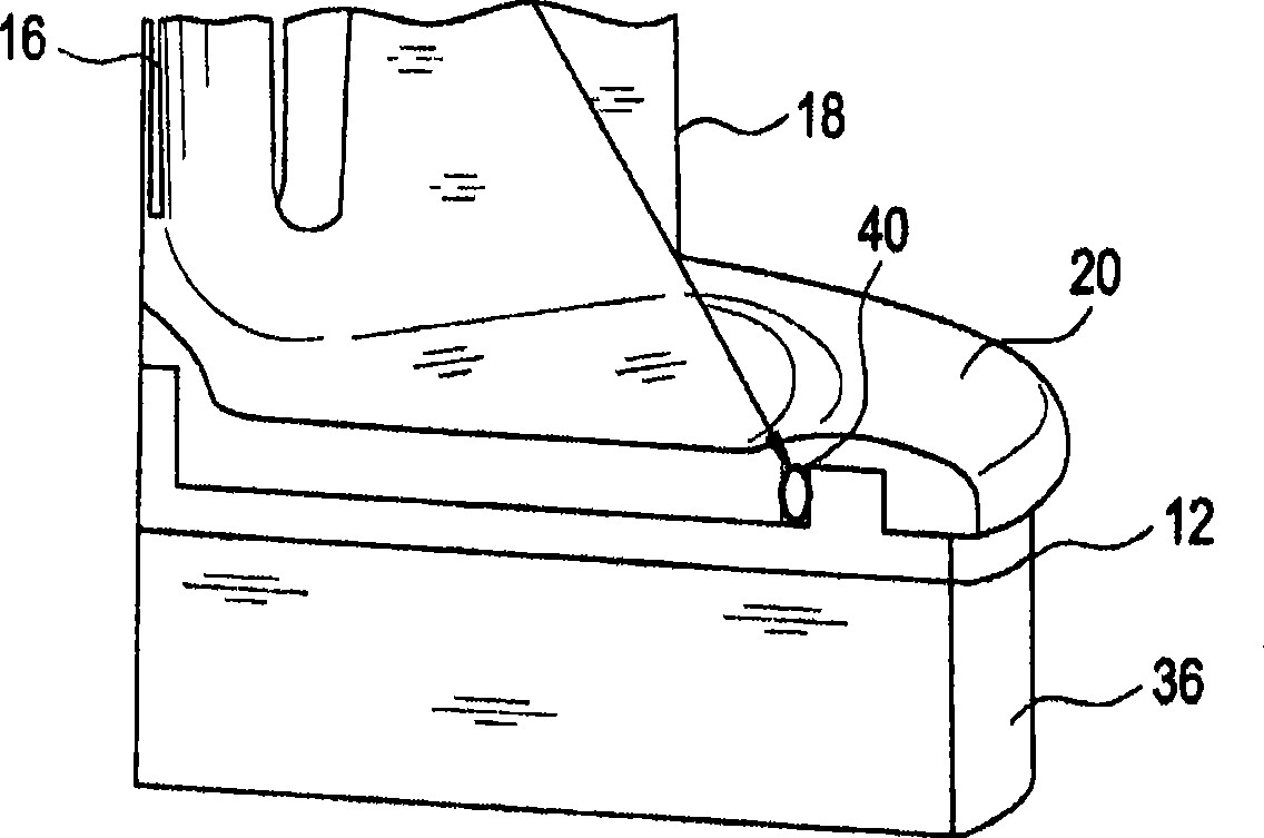
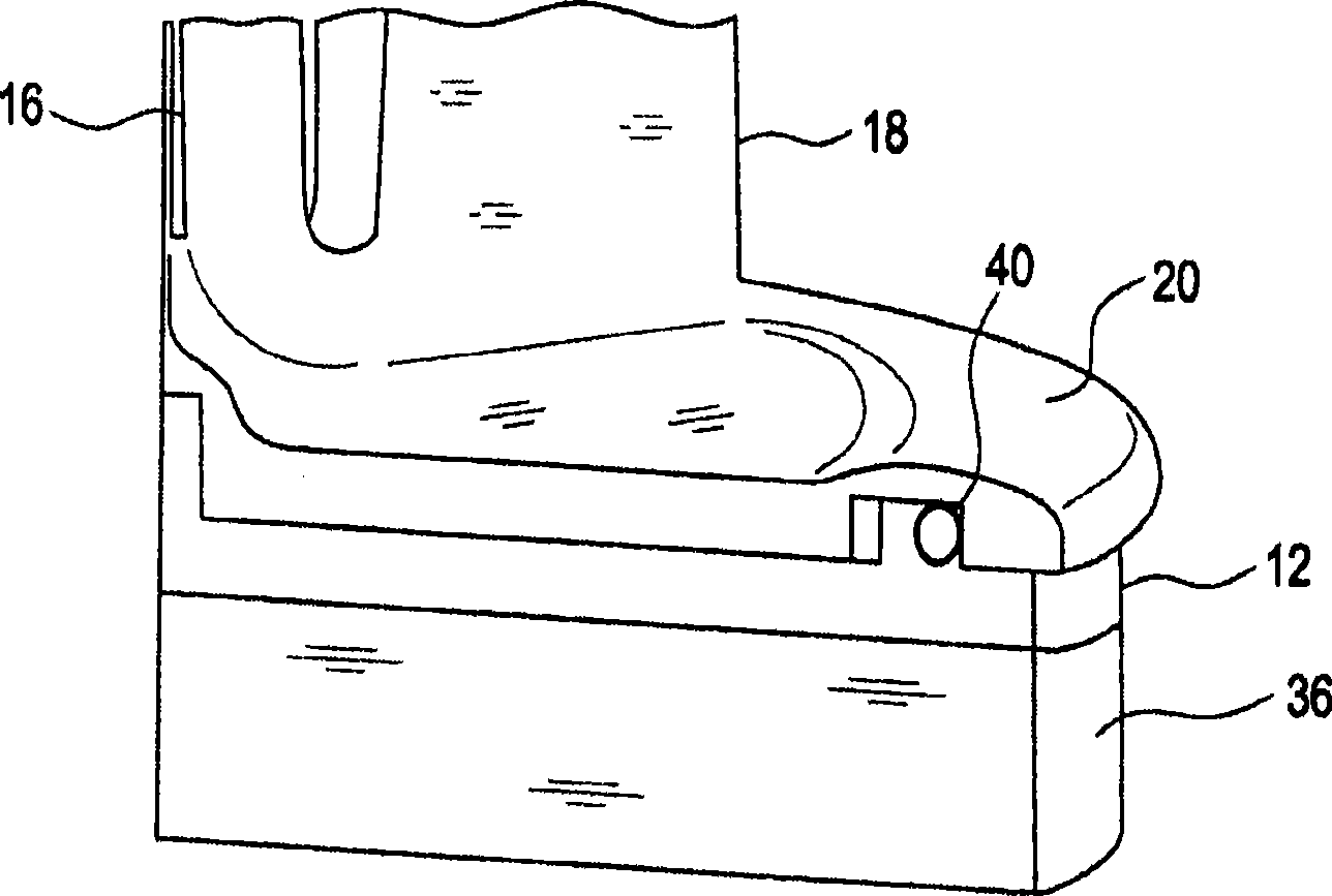
[0019] The present application discloses an apparatus and method for effectively sealing the interface between a shell mold and a chill plate in a casting pattern assembly. figure 1 A cutaway perspective view of the mold assembly 10 on a chill plate 12 is shown. Mold assembly 10 generally includes an opening 14 , eg, funnel-shaped, in fluid communication with a runner 16 that is in fluid communication with one or more shell molds 18 . The shell mold, or cavity, defines the shape of the part to be cast. A mold assembly having more than one shell mold is often referred to as a cluster mold assembly. A skirt 20 extends laterally across the bottommost portion of the mold assembly. A groove (ie channel) 22 is formed in the bottom surface of the skirt such that the shell mold 18 is contained within the perimeter defined by the groove, ie the channel defines the boundary of the shell mold.

[0020] In one embodiment, the chill plate 12 includes a generally planar surface 24 and pr...


PUM


Abstract

Processes for directionally casting liquid metal to form an articles is disclosed, which includes compressing a seal intermediate a mold chill plate and a mold assembly, wherein the seal circumscribes a shell mold in the mold assembly; filling the shell mold in the mold assembly with molten metal; immersing the mold assembly into a liquid metal cooling bath from a bottom portion to a top portion of the mold assembly; and transmitting heat from the mold assembly to the liquid metal cooling bath to solidify the molten metal from the bottom portion to the top portion of the mold assembly. A device for directionally casting liquid metal is further provided.

Description

technical field [0001] The present disclosure generally relates to an apparatus and method for casting an article, and in particular, the present invention relates to an apparatus and method for orienting a casting article. Background technique [0002] Certain components, such as turbine buckets and stator blades for gas turbine engines, are typically manufactured using directional solidification casting. In this method, a dedicated shell mold is constructed for the particular part being cast, such as a turbine bucket or blade. [0003] Directional solidification casting can increase the strength of these parts by obtaining single crystal parts. Here, the mold assembly generally includes a shell mold (cavity) and a chill plate, wherein the chill plate is located at the lowest position of the mold assembly. The entire mold assembly is then raised into a heating chamber where it is preheated and subsequently filled with the desired superalloy in a superheated liquid melt st...

Claims


Application Information

Patent Timeline
Patent Type & Authority Applications(China)
IPC IPC(8): B22D27/04B22C9/00
CPCB22D27/045
Inventor 黄世钦A·J·埃利奥特M·F·X·吉格利奥蒂A·M·马金德R·J·彼得森S·F·鲁特科夫斯基
Owner GENERAL ELECTRIC CO
Why Eureka
Try Eureka