
Self-wind cooled rotor double stator low torque ripple magneto resistance genus motor

A torque pulsation, double-stator technology, applied in the direction of cooling/ventilation devices, magnetic circuit rotating parts, electric components, etc., can solve the problems affecting the life of the winding, the temperature rise of the stator and rotor, and the inoperability of the motor, so as to improve the saturation The effects of magnetic density selection, reduced heat dissipation area, and reduced volume and weight

Inactive Publication Date: 2009-05-20
NANJING UNIV OF AERONAUTICS & ASTRONAUTICS
View PDF0 Cites 1 Cited by
  • Summary
  • Abstract
  • Description
  • Claims
  • Application Information

AI Technical Summary

Problems solved by technology

However, since the reluctance motor realizes the conversion of electromechanical energy through the change of reluctance, and the magnetic flux of its stator and rotor are alternating, it has obvious eddy current loss and relatively low efficiency. obvious temperature rise
This will affect the life of the winding if it is light, and it will damage the winding if it is heavy, making the motor unable to run
The usual method is to reduce the current density of the winding, reduce the magnetic flux density of the magnetizer, and increase the external heat dissipation area to reduce the temperature rise, but this will increase the volume and weight of the motor and cause production waste.
This limits the scope of application of this type of motor, especially in high-power applications

Method used


Image

  • Self-wind cooled rotor double stator low torque ripple magneto resistance genus motor
  • Self-wind cooled rotor double stator low torque ripple magneto resistance genus motor
  • Self-wind cooled rotor double stator low torque ripple magneto resistance genus motor

Examples


Embodiment Construction

[0029] specific implementation plan

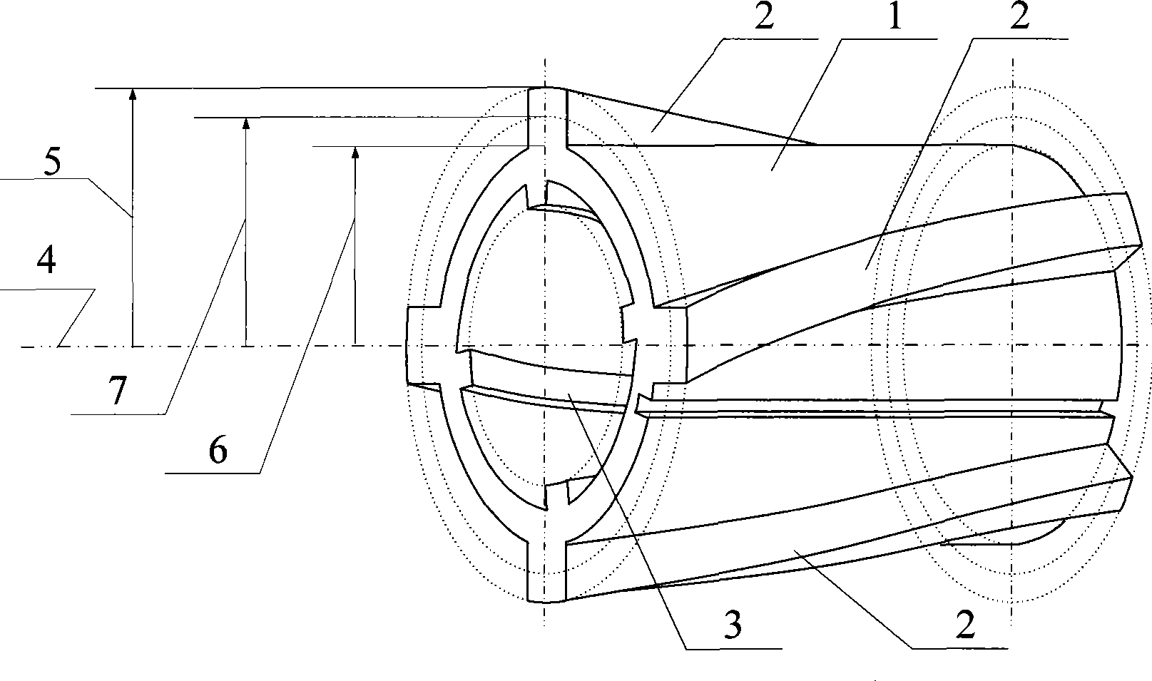
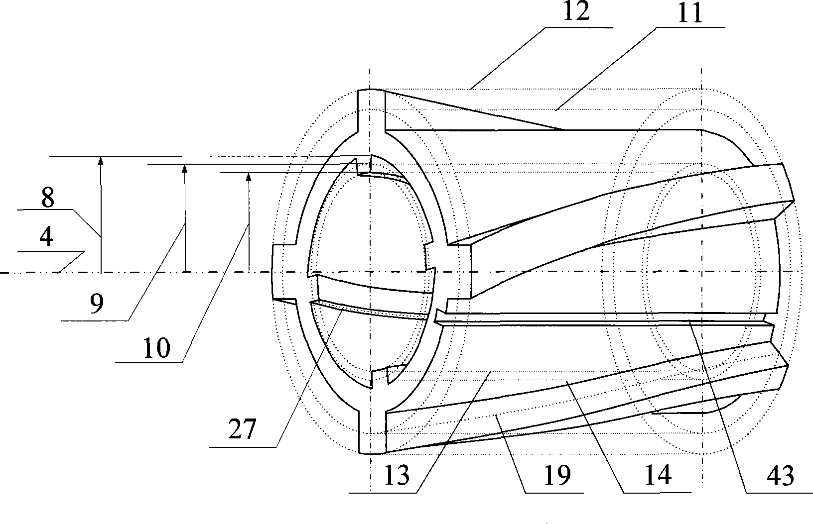
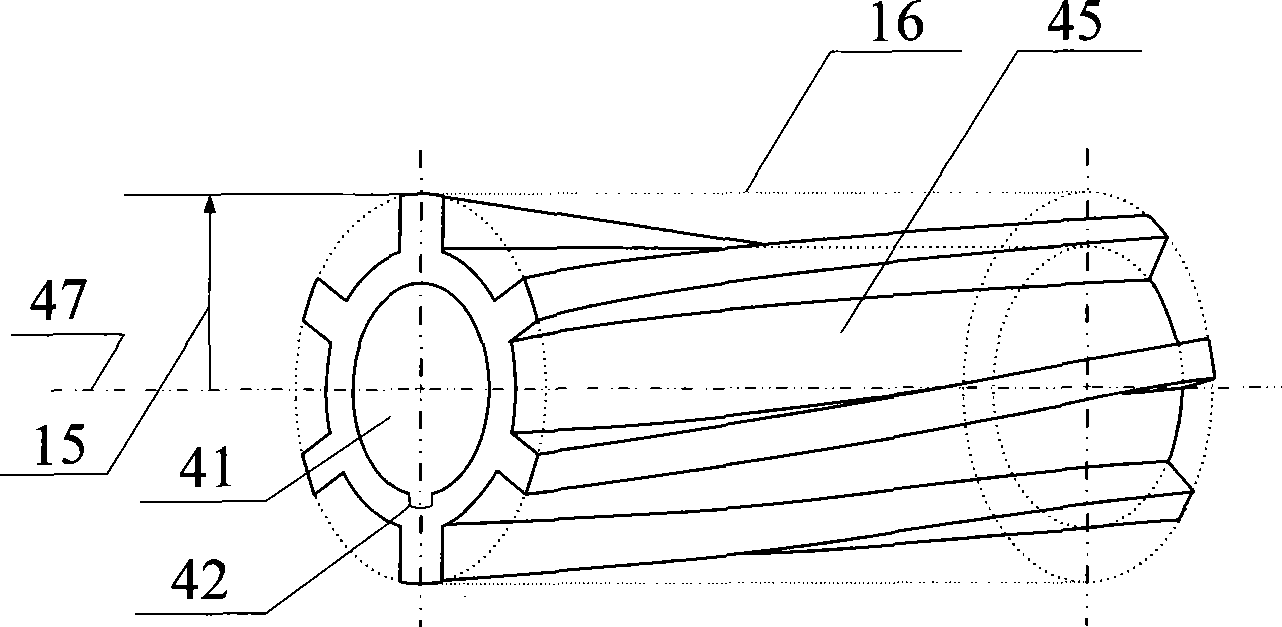
[0030] Taking the double salient pole motor as an example, since the rotor of the double salient pole motor has only salient pole teeth and tooth slots, and no windings, the present invention proposes the use of salient pole Due to the structural characteristics of teeth and cogging, the salient pole teeth of the double salient pole motor rotor are designed as the blade structure shape of the axial flow fan, so that the air around one end of the rotor (intake end) can be sucked into the rotor teeth of the motor when the rotor rotates. Slot, and then go out from the other end of the rotor (air outlet), directly take away the heat generated by the motor rotor to cool the motor. In order to achieve this purpose, the shape of the salient pole teeth of the rotor can be designed according to the working principle of the blades of the axial flow fan.

[0031] figure 1 and figure 2 The rotor structure diagram of the 6 / 4 / 4 / 6-pole self-wind-cool...


PUM


Abstract

The invention relates to a natural wind-cooled rotor double-stator low-torque ripple reluctance motor, which belongs to a reluctance motor. The motor comprises a rotor and inner and outer stators, wherein inner and outer salient-pole teeth of the rotor are titled teeth which are in the structural shape of fan blades of an axial-flow fan and determined by an air inlet angle beta equal to tan<-1>(C / U) and an air outlet angle alpha equal to tan<-1>(C / (U-C2u)), wherein C represents the absolute speed of inlet air, U represents rim speed, C2u is equal to Lu / U, and Lu is rim power. Salient-pole tooth structural shapes of the inner and outer two stators ensure the performance of the motor is consistent with that of the prior rotor titled-tooth inner-outer double stator double-salient pole motor. When the motor rotates, the structural shape of axial-fan blade of the inner and outer salient-pole teeth of the rotor and the structural shapes of axial-fan blade of the inner and outer salient-pole teeth of the inner and outer stators generate air suction force concertedly to draw the air into the motor and discharge the air through an air outlet to remove heat generated by the rotor of the motor, so the self-cooling of the motor is realized, the design of the motor is optimized, and the volume and weight of the motor are reduced.

Description

technical field [0001] The invention relates to a self-wind-cooled rotor double-stator low-torque pulsating reluctance motor, including switched reluctance motors, double-salient pole motors, induction motors, etc., and belongs to the technical field of motors. Background technique [0002] The reluctance motor realizes the conversion of electromechanical energy through the change of reluctance. Such motors mainly include switched reluctance motors, doubly salient motors, and induction motors. Taking the double salient pole motor as an example, the rotor is punched and laminated with silicon steel sheets, and there is a salient pole structure on the rotor, no winding, no brush, so this type of motor has the outstanding advantages of simple structure and reliable operation, especially suitable for Run at high speed. In addition, electrically excited doubly salient motors also have the advantage of relatively low excitation power, so doubly salient motors have broad applicat...

Claims


Application Information

Patent Timeline
Patent Type & Authority Applications(China)
IPC IPC(8): H02K16/04H02K1/24H02K1/14H02K9/00H02K29/00
Inventor 马运东王爽王俊琦周正贵杨宏
Owner NANJING UNIV OF AERONAUTICS & ASTRONAUTICS
Learn More