Single-phase multiple-parameter electric power instrument
A power meter and multi-parameter technology, applied in the direction of multi-tester circuits, etc., can solve problems such as difficult linearity requirements, affect mass production, and accuracy cannot be guaranteed, and achieve high test accuracy, low power consumption, and multiple measurement parameters. Effect
- Summary
- Abstract
- Description
- Claims
- Application Information
AI Technical Summary
Problems solved by technology
Method used
Image
Examples
Embodiment Construction
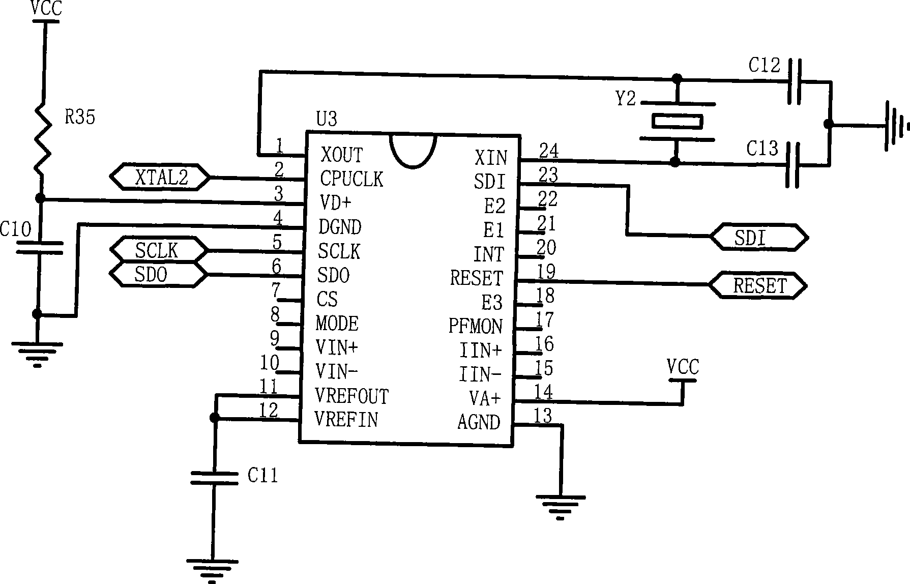
[0016] see figure 2 , The sampling circuit is composed of voltage input circuit and current input circuit. Among them, the voltage input circuit can adapt to 0-100V, 0-220V, 0-380V; the current input circuit can adapt to 0-5A. The voltage signal terminals Uin*, Uin are connected to the measured voltage signal, and the voltage signal obtains the primary current through the resistors R38, R37, and voltage transformer TV1. If the input voltage signal is 220V, and the resistors R38, R37 are 110kΩ, the primary current is 1mA. The 1:1 voltage transformer TV1 generates an AC voltage of 50mV on the resistor R25 (50Ω), because the resistance of R25 is much smaller than the resistance of R26+R27 (2kΩ), so the accuracy and stability are determined by the resistors R37, R38, and R25. Resistors R25, R26, R27, R28 and capacitors C4, C5, C8 form a filter phase-shifting circuit, through the terminal Vin + 、Vin - Connected with the electric power measuring circuit, it is advisable to take 0...
PUM
 Abstract
Description
Claims
Application Information
 - R&D
- Intellectual Property
- Life Sciences
- Materials
- Tech Scout
- Unparalleled Data Quality
- Higher Quality Content
- 60% Fewer Hallucinations
Browse by: Latest US Patents, China's latest patents, Technical Efficacy Thesaurus, Application Domain, Technology Topic, Popular Technical Reports.
© 2025 PatSnap. All rights reserved.Legal|Privacy policy|Modern Slavery Act Transparency Statement|Sitemap|About US| Contact US: help@patsnap.com


