Withdrawal roll device of end trimming shear

A technology of pinch rollers and trimming shears, which is applied in the field of pinch equipment before and after trimming and shearing, can solve the problems of poor linear speed of roller surfaces, marks of handover dislocation, affecting the shape and quality of steel plates, etc.

Inactive Publication Date: 2009-05-20
ERZHONG GROUP DEYANG HEAVY EQUIP
View PDF0 Cites 6 Cited by
  • Summary
  • Abstract
  • Description
  • Claims
  • Application Information

AI Technical Summary

Problems solved by technology

The disadvantages of the pinch rollers in the above form are: when the pinch rollers are frequently started and stopped (the nominal maximum value can reach 1800 times/hour) to convey the steel plate, due to the large number of motors, and the inherent mechanical properties of each motor It is difficult to ensure the consistency of the characteristics, which causes a large roller surface line speed diffe

Method used


Image

  • Withdrawal roll device of end trimming shear

Examples


Embodiment Construction

[0013] The present invention will be further described below in conjunction with the accompanying drawings.

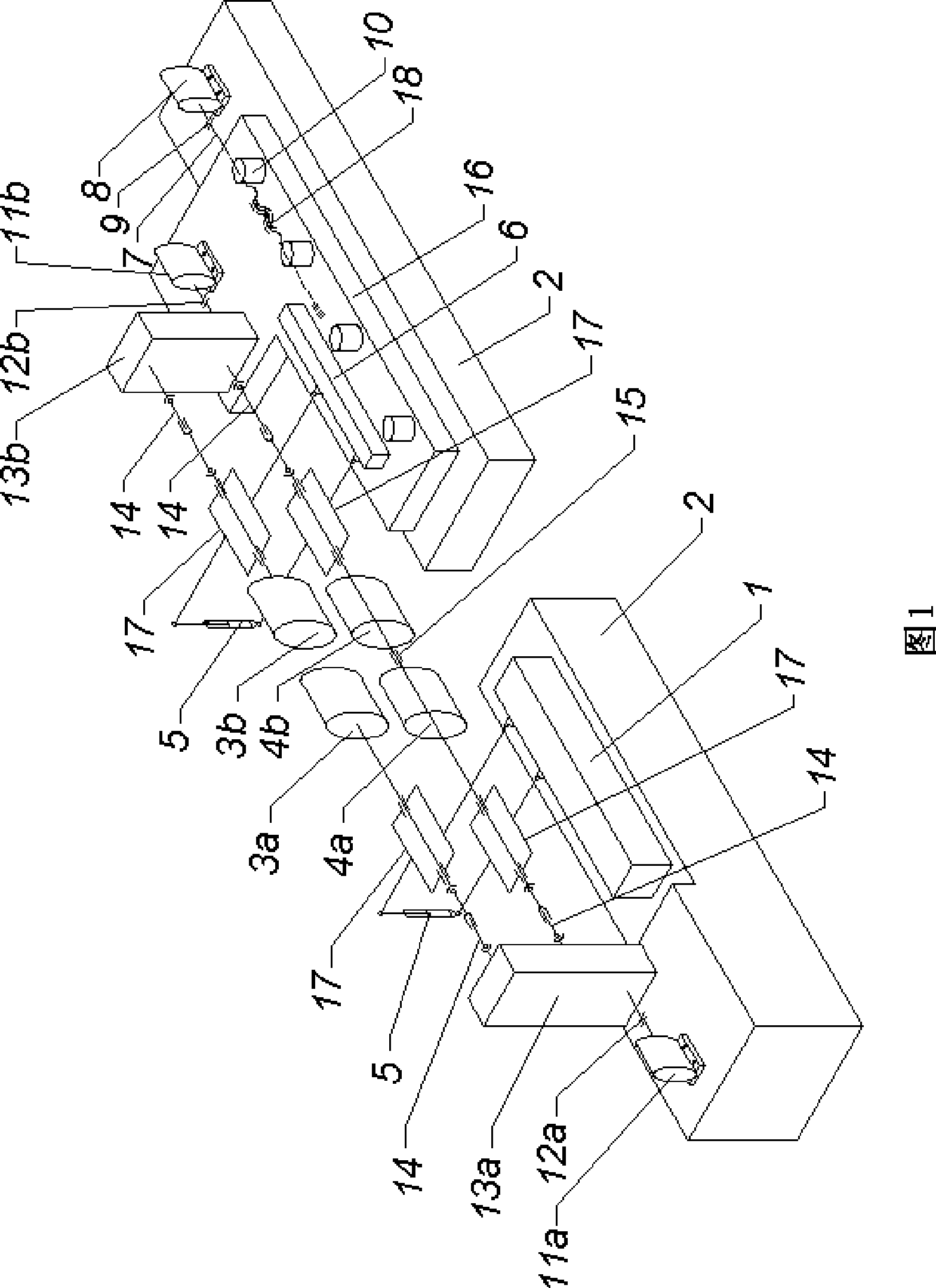
[0014] The trimming shear pinch roller device as shown in Figure 1, comprises the upper pinch roller 3a of the fixed side, the lower pinch roller 4a of the fixed side, the upper pinch roller 3b of the moving side, the lower pinch roller 4b of the moving side, the lower pinch roller of the fixed side The pinch roller 4a and the lower pinch roller 4b on the moving side are axially connected by a synchronous shaft 15, the upper pinch roller 3a on the fixed side and the lower pinch roller 4a on the fixed side are synchronously driven by the transmission mechanism, and the upper pinch roller on the moving side 3b and the lower pinch roller 4b on the moving side are synchronously driven by a transmission mechanism. The pinch roller 3a on the fixed side and the lower pinch roller 4a on the fixed side are two upper and lower pinch rollers relative to each other, and the upper ...


PUM


Abstract

The invention discloses an end trimming shears pinch roll device on a steel rolling production line of medium plates. The device can prevent the phenomenon that steel plates 'are pulled to one side' during conveying. The end trimming shears pinch roll device comprises a fixed side upper pinch roll, a fixed side lower pinch roll, a movable side upper pinch roll and a movable side lower pinch roll, wherein the fixed side lower pinch roll is axially connected with the movable side lower pinch roll through a synchronous shaft; the fixed side upper pinch roll and the fixed side lower pinch roll are synchronously driven by a driving mechanism; and the movable side upper pinch roll and the movable side lower pinch roll are synchronously driven by a driving mechanism, so that the end trimming shears pinch roll device can guarantee consistent linear velocity of roll surfaces between two opposite upper and lower pinch rolls, avoid the phenomenon that the steel plates are 'pulled to one side' during the conveying, and improve the quality of the steel plates sheared by a pair of end trimming shears.

Description

technical field [0001] The invention relates to front and rear pinch equipment of trimming shears on a metallurgical plate rolling production line, in particular to a pinch roll device of edge trimming shears on a medium-thick plate rolling production line. Background technique [0002] The existing trimming shear pinch roll device used in the medium and heavy plate rolling production line generally adopts the following structure and driving form: it includes a fixed side pinch roll and a moving side pinch roll, and the fixed side pinch roll is pinched by the fixed side. The pinch roller on the moving side is composed of the upper pinch roller on the moving side and the lower pinch roller on the moving side. Each pinch roller is independently driven by a motor with a reducer. The upper and lower opposite pinch rollers are controlled by an electrical system to run synchronously. The upper and lower opposite pinch rollers rely on hydraulic cylinders to change the size and size...

Claims


Application Information

Patent Timeline
IPC IPC(8): B21D43/09
Inventor 漆小虎郑永红叶洪生李聃
Owner ERZHONG GROUP DEYANG HEAVY EQUIP
Why Eureka
Try Eureka