
Gas path control method and device

A gas circuit and controller technology, which is applied in the direction of measuring devices, flow control of electric devices, instruments, etc., can solve the problems of long time to complete ventilation stabilization, poor etching effect of wafers, large feedback error, etc., and achieve fast and stable Effect of gas output and shut-off, reduction of hardware operation time, weakening of adjustment time

Active Publication Date: 2009-05-06
BEIJING NAURA MICROELECTRONICS EQUIP CO LTD
View PDF0 Cites 7 Cited by
  • Summary
  • Abstract
  • Description
  • Claims
  • Application Information

AI Technical Summary

Problems solved by technology

[0005] 1. The general air circuit includes both valves and MFCs, and the time from receiving control commands to execution of pneumatic valves is much shorter than the time from receiving control commands to execution of MFCs (internal delay), resulting in the action time of controlled devices Can not control
[0006] 2. Due to the above-mentioned simple control, there will be a large pressure difference between the gas at both ends of the MFC every time the ventilation is performed, and because the MFC uses PID calculation, resulting in a large feedback error, resulting in a longer time for the stable ventilation to complete. Long, inefficient process
[0007] Furthermore, due to the unstable factors of ventilation, it is difficult to apply RF voltage for gas ignition, and it will have a certain impact on the process, resulting in poor etching of the wafer (also known as the first chip effect).

Method used

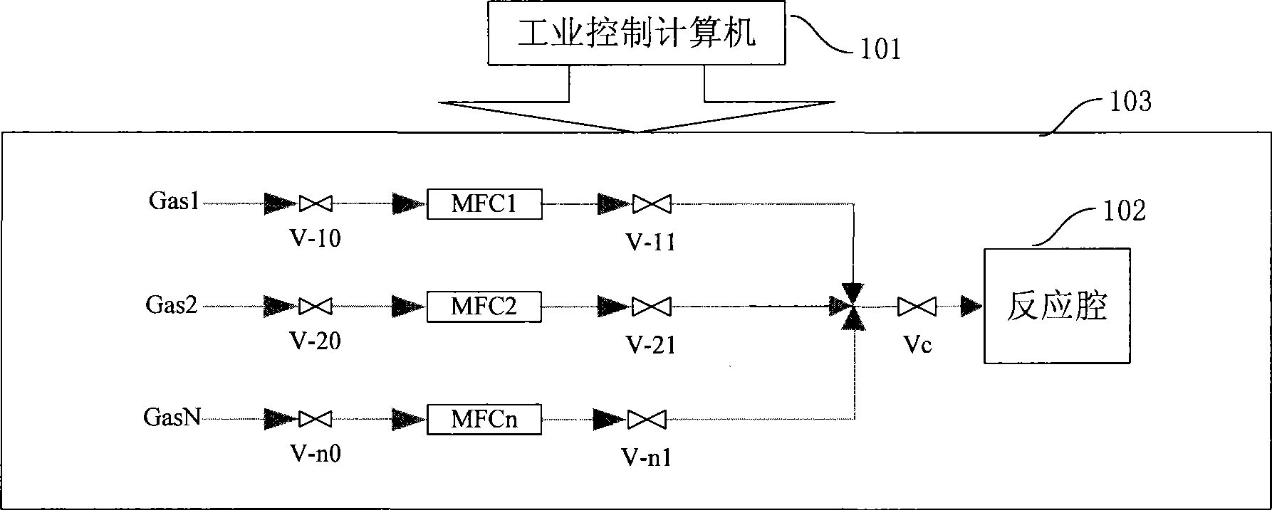
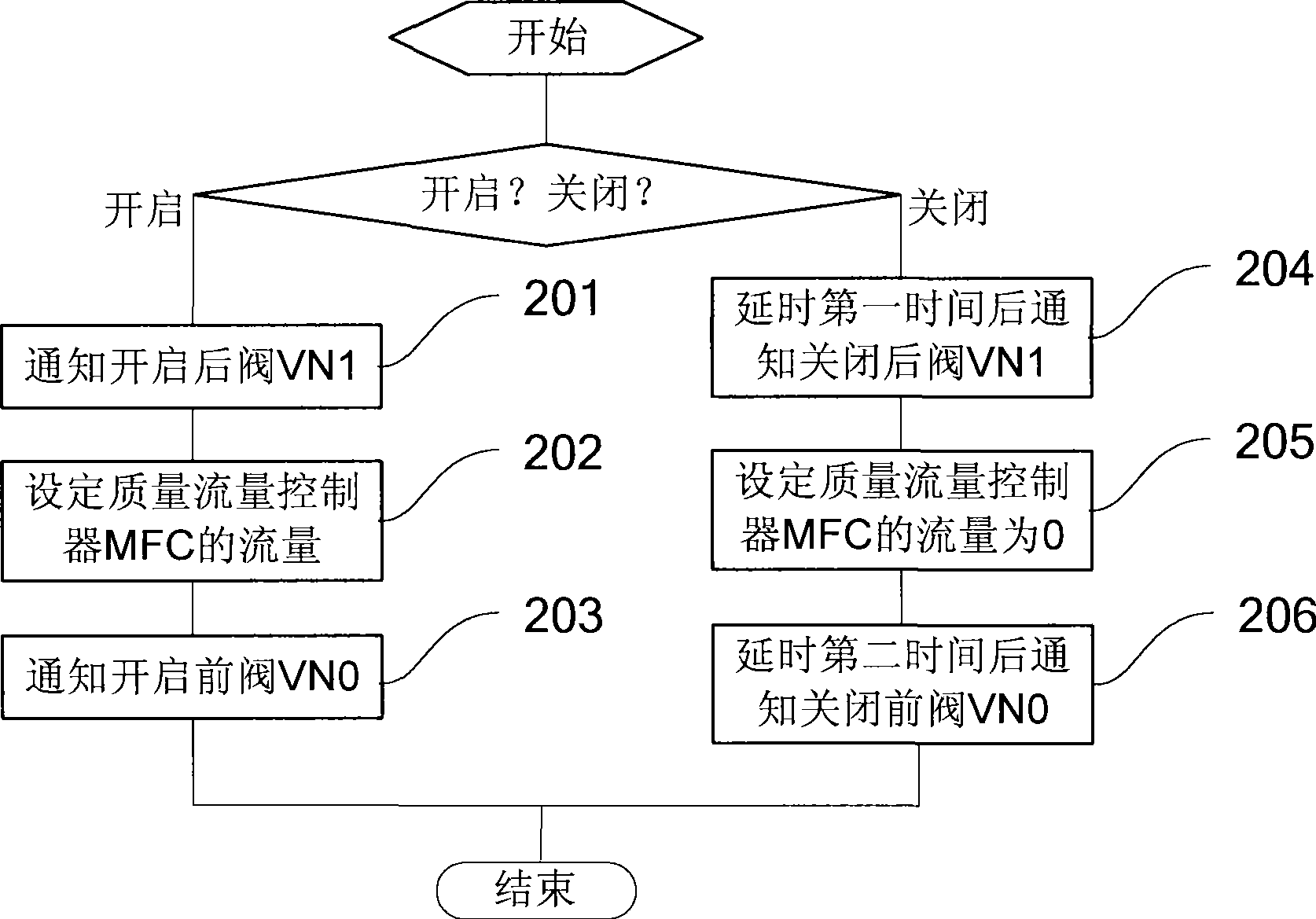
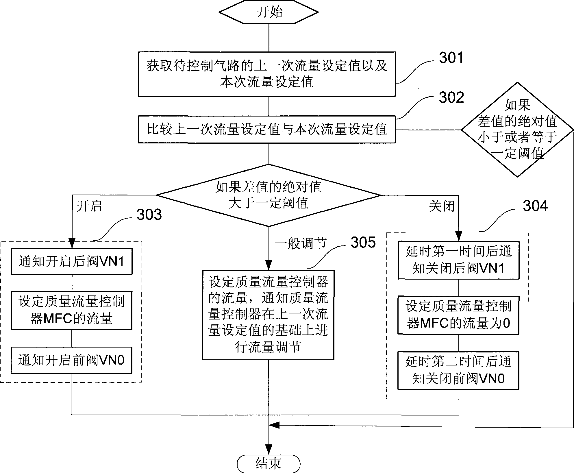

Image

  • Gas path control method and device
  • Gas path control method and device
  • Gas path control method and device

Examples


Embodiment Construction

[0053] In order to make the above objects, features and advantages of the present invention more comprehensible, the present invention will be further described in detail below in conjunction with the accompanying drawings and specific embodiments.

[0054] The invention is applicable to numerous general purpose and special purpose computing system environments or configurations. Examples: personal computers, server computers, handheld or portable devices, tablet-type devices, multiprocessor systems, microprocessor-based systems, set-top boxes, programmable consumer electronics, network PCs, minicomputers, mainframe computers, including A distributed computing environment for any of the above systems or devices, etc.

[0055] The invention may be described in the general context of computer-executable instructions, such as program modules, being executed by a computer. Generally, program modules include routines, programs, objects, components, data structures, etc. that perfo...


PUM


Abstract

The invention provides a gas path control method and a device thereof. The method comprises: when the operation of opening a gas path is executed, the following operations are executed aiming at a front valve, a rear valve and a quality flow controller of the gas path: the rear valve is informed to open; the flow of the quality flow controller is set; the front valve is informed to open; when the operation of closing the gas path is executed, the following operations are executed aiming at the front valve, the rear valve and the quality flow controller of the gas path: the flow of the quality flow controller is set to 0; the rear valve is informed to close after the preset first time is delayed, the sum of the first time and the delay time of the inner part of the rear valve is less than the delay time of the inner part of the quality flow controller; the front valve is informed to close after the preset second time is delayed, the sum of the second time and the delay time of the inner part of the front valve is more than the delay time of the inner part of the quality flow controller. The invention can effectively avoid the output shock problem of an MFC when having the pressure difference, weakens the first piece effect of unstable ventilation, and achieves better control effect.

Description

technical field [0001] The invention relates to the technical field of industrial process control, in particular to a method and device for controlling gas circuits. Background technique [0002] In industrial process control, the control of gas flow is an important part. For example, in the semiconductor industry, by controlling a certain flow rate of the gas and applying radio frequency power, the purpose of causing the gas to glow in the reaction chamber is achieved. Since the stability of the gas flow rate directly affects the gas initiation and process results, the gas flow rate is generally controlled by a mass flow controller in the prior art. [0003] A gas flow regulating valve is set in the mass flow controller (MFC), and the valve can adjust the flow through the controller from zero to the full scale of the measurement. MFC generally adopts PID control, and PID control is based on the error of the system, using proportional, integral, and differential to calcula...

Claims


Application Information

Patent Timeline
IPC IPC(8): G05D7/06
CPCG01T1/2985
Inventor 付金生
Owner BEIJING NAURA MICROELECTRONICS EQUIP CO LTD
Learn More