
Heat radiating mechanism

A technology of heat dissipation mechanism and heat dissipation main body, which is applied in the direction of cooling/ventilation/heating transformation, semiconductor/solid-state device parts, semiconductor devices, etc., and can solve the problems of heat dissipation and conduction efficiency limitation, small cross-sectional area of ​​conduction and heat conduction, and falling off of heat dissipation mechanism, etc. , to achieve the effect of improving electrical and thermal conductivity, increasing the conductive cross-sectional area, and combining tightly and stably

Active Publication Date: 2009-04-29
LITE ON TECH CHANG ZHOU CO LTD +2
View PDF0 Cites 3 Cited by
  • Summary
  • Abstract
  • Description
  • Claims
  • Application Information

AI Technical Summary

Problems solved by technology

For some electronic components that are prone to high heat, in order to dissipate heat effectively and quickly, they can also be fixed on the heat dissipation mechanism, and the heat dissipation mechanism with good thermal conductivity can assist the heat dissipation of the electronic components. However, the traditional heat dissipation mechanism is used to There are very few filling holes for conductive materials, generally only one, and only 1-2 long pins are combined with the printed circuit board. Once any solder joint is loose, it is easy to cause the entire heat dissipation mechanism to fall off, and the connection is not good. stable
On the other hand, because there are too few filling holes, there are few conductive materials that can be filled, and the conduction and heat conduction cross-sectional area is small, so the heat dissipation and conduction efficiency will be limited.

Method used


Image

  • Heat radiating mechanism
  • Heat radiating mechanism
  • Heat radiating mechanism

Examples


Embodiment Construction

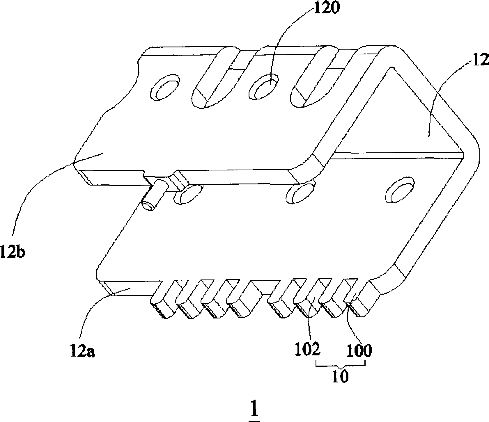
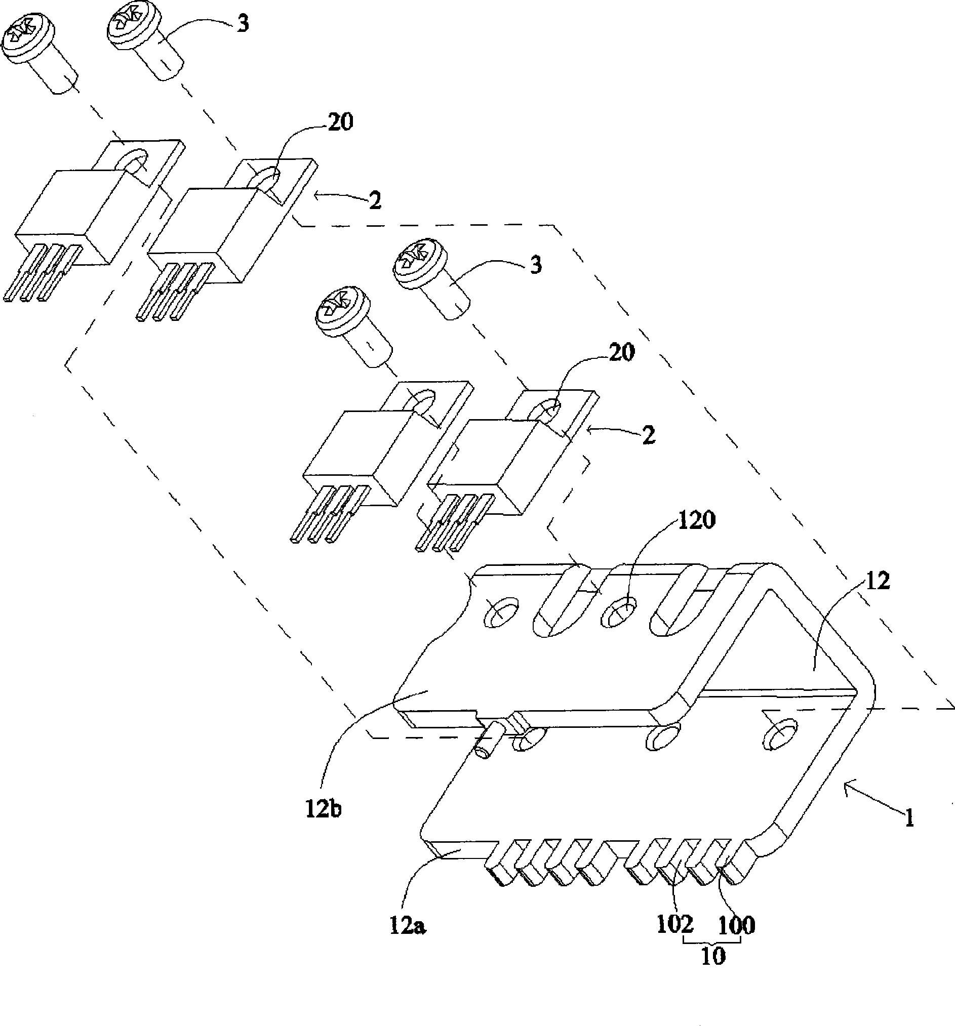
[0015] refer to figure 1 and figure 2 As shown, the present invention provides a heat dissipation mechanism 1, which can be fixed on the printed circuit board 4, and is used to conduct electricity and dissipate heat to the electronic components loaded thereon. The heat dissipation mechanism 1 includes a heat dissipation main body 12 and an extended The connecting portion 10 is provided, wherein the connecting portion 10 has a plurality of pins 100 spaced apart from each other, and the heat dissipation mechanism 1 is electrically connected to the printed circuit board 4 through the pins 100 .

[0016] refer to figure 1 As shown, in one embodiment of the present invention, the heat dissipation mechanism 1 is arched, the heat dissipation body 12 has two end arms 12a and 12b parallel to each other, and the connecting part 10 is extended from the ends of the end arms 12a , the connecting portion 10 includes a plurality of pins 100 spaced apart from each other for electrical conn...


PUM


Abstract

The invention relates to a radiating mechanism used for radiating for an electronic element which is arranged on the radiating mechanism; the radiating mechanism is provided with a radiating body and an interconnecting piece which are mutually connected, the interconnecting piece is provided with a plurality of pins, the radiating mechanism can be fixed on a print circuit board by the pins, the pins are mutually spaced, a filling opening is formed between each two adjacent pins and is filled with conducting material. In the radiating mechanism of the invention, a cellular type interconnecting piece is electrically connected with the print circuit board; the interconnecting piece is provided with a plurality of pins and is inserted and connected with corresponding inserting holes of the print circuit board by a plurality of pins, thus the radiating mechanism and the print circuit board can be jointed more tightly and steadily; furthermore, the more the filling openings are formed, the more conducting material is filled, thus increasing the conducting section area, reducing the resistance between the radiating mechanism and the print circuit board and effectively improving the electricity conducting efficiency and heat conducting efficiency.

Description

technical field [0001] The invention relates to a heat dissipation mechanism, in particular to a heat dissipation mechanism for heat dissipation of electronic components. Background technique [0002] During the working process of electrical appliances, some of the electronic components will generate high heat. If the heat cannot be dissipated for a long time, the electronic components in the high temperature environment are often difficult to work normally, which will affect the operation of the electrical appliances. In order to dissipate heat from electronic components in a timely manner, people have adopted various means of heat dissipation, such as accelerating the internal and external air circulation through fans to reduce the overall internal working temperature. For some electronic components that are prone to high heat, in order to dissipate them effectively and quickly, they can also be fixed on the heat dissipation mechanism, and the heat dissipation mechanism wi...

Claims


Application Information

Patent Timeline
Patent Type & Authority Applications(China)
IPC IPC(8): H05K7/20H01L23/367
CPCH01L2023/4031H01L23/4006H01L23/367H01L2023/405H01L2924/0002H01L2924/00
Inventor 李永洲
Owner LITE ON TECH CHANG ZHOU CO LTD
Learn More