System for delivering air from a multi-stage compressor to a turbine portion of a gas turbine engine

A gas turbine and compressor technology, applied in the direction of gas turbine devices, mechanical equipment, engine components, etc.

Active Publication Date: 2009-04-29
GENERAL ELECTRIC TECH GMBH
View PDF3 Cites 12 Cited by
  • Summary
  • Abstract
  • Description
  • Claims
  • Application Information

AI Technical Summary

Problems solved by technology

For this reason, make-up air is typically limited to intermediate compressor stages

Method used


Image

  • System for delivering air from a multi-stage compressor to a turbine portion of a gas turbine engine

Examples


Embodiment Construction

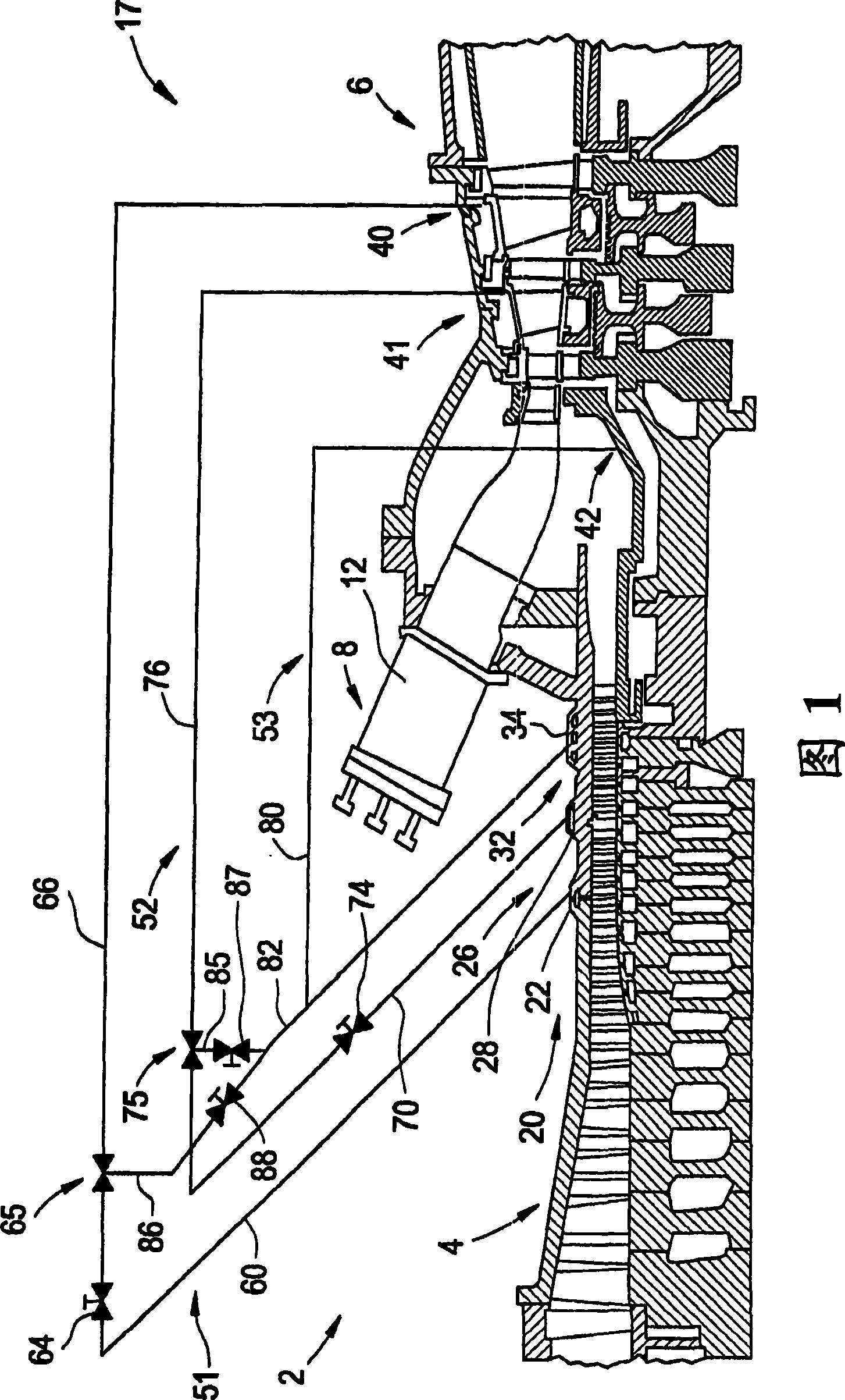
[0043] Referring first to FIG. 1 , there is indicated generally at 2 a gas turbine engine constructed in accordance with an exemplary embodiment of the present invention. Engine 2 includes a compressor 4 operably connected to a turbine 6 via a shaft (not separately labeled). Engine 2 is also shown to include a combustor assembly 8 that includes a combustion chamber 12 . As will be discussed more fully below, combustion gases are generated in combustor assembly 8 and used to drive turbine 6 .

[0044] In operation, air flows into the compressor 4 and is compressed into a high pressure gas. This high pressure gas is fed to the burner assembly 8 and mixed with fuel such as process gas and / or synthetic gas (syngas). A fuel / air or combustible mixture is introduced into combustor 12 and ignited to form a high pressure, high temperature combustion gas stream with a temperature of from about 871 degrees Celsius (°C) to 1621°C (1600°F (°F) to 2950°F). Alternatively, combustor assemb...


PUM


Abstract

A system for providing air from a multi-stage to a turbine includes a turbine having a high pressure input port and a low pressure input port. The system also includes a compressor having at least one high pressure extraction air output and at least one low pressure extraction air output. A valve is fluidly connected to the at least one high pressure extraction air output, at least one low pressure extraction air output and low pressure input port of the turbine. The valve is selectively operated to fluidly connect the at least one low pressure extraction air output with the low pressure input port during normal operating conditions and fluidly connect the at least one high pressure extraction air output and the low pressure input port during a turn down condition or below design temperature operation to enhance turbine engine performance.

Description

technical field [0001] The present invention relates to gas turbine engine technology, and more particularly, to a system for delivering air from a multi-stage compressor to the turbine section of a gas turbine engine for operation at turn down and / or below design temperature During this period, the performance of the turbo engine is enhanced. Background technique [0002] Turbine engines are designed to run at full speed under International Organization for Standardization (ISO) conditions. That is, a turbine engine is designed to operate in a specified speed band using a specified range of input conditions such as design point temperature, barometric pressure, fuel type, etc., to produce an optimally high output, between which The following operations are inefficient. However, input conditions are often outside the range of the design point, and / or less than full output is desired. During ISO operation, air is injected into the combustor to mix with fuel, creating high-...

Claims


Application Information

Patent Timeline
Patent Type & Authority Applications(China)
IPC IPC(8): F02C7/057
CPCF02C6/08F01D25/12
Inventor E·D·罗什W·A·帕克
Owner GENERAL ELECTRIC TECH GMBH
Why Eureka
Try Eureka