Flat-shaped groove heat exchange tube and heat exchanger using the same
A technology of heat exchange tubes and flat shapes, which is applied in the field of flat grooved heat exchange tubes and heat exchangers using flat grooved heat exchange tubes, which can solve the problems of reduced heat exchange efficiency of heat exchangers and achieve heat exchange Improved effect, less deformation, and reduced maintenance costs
Active Publication Date: 2010-11-10
BEIJING U BRIDGE CHAOYANG
View PDF0 Cites 1 Cited by
- Summary
- Abstract
- Description
- Claims
- Application Information
AI Technical Summary
Problems solved by technology
If the heat exchange tubes are too dense, the two bulging heat exchange tubes may squeeze together, blocking the flow of the heat exchange medium outside the heat exchange tubes, resulting in a decrease in the overall heat exchange efficiency of the heat exchanger
Need to propose a new type of heat exchange tube to overcome the shortcomings of heat exchange tube deformation
Method used
View moreImage
Smart ImageViewing Examples
Examples
Embodiment 1
Embodiment 2
Embodiment 3
Login to View More PUM
 Abstract
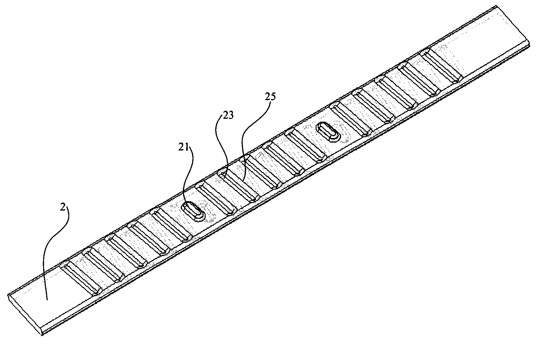
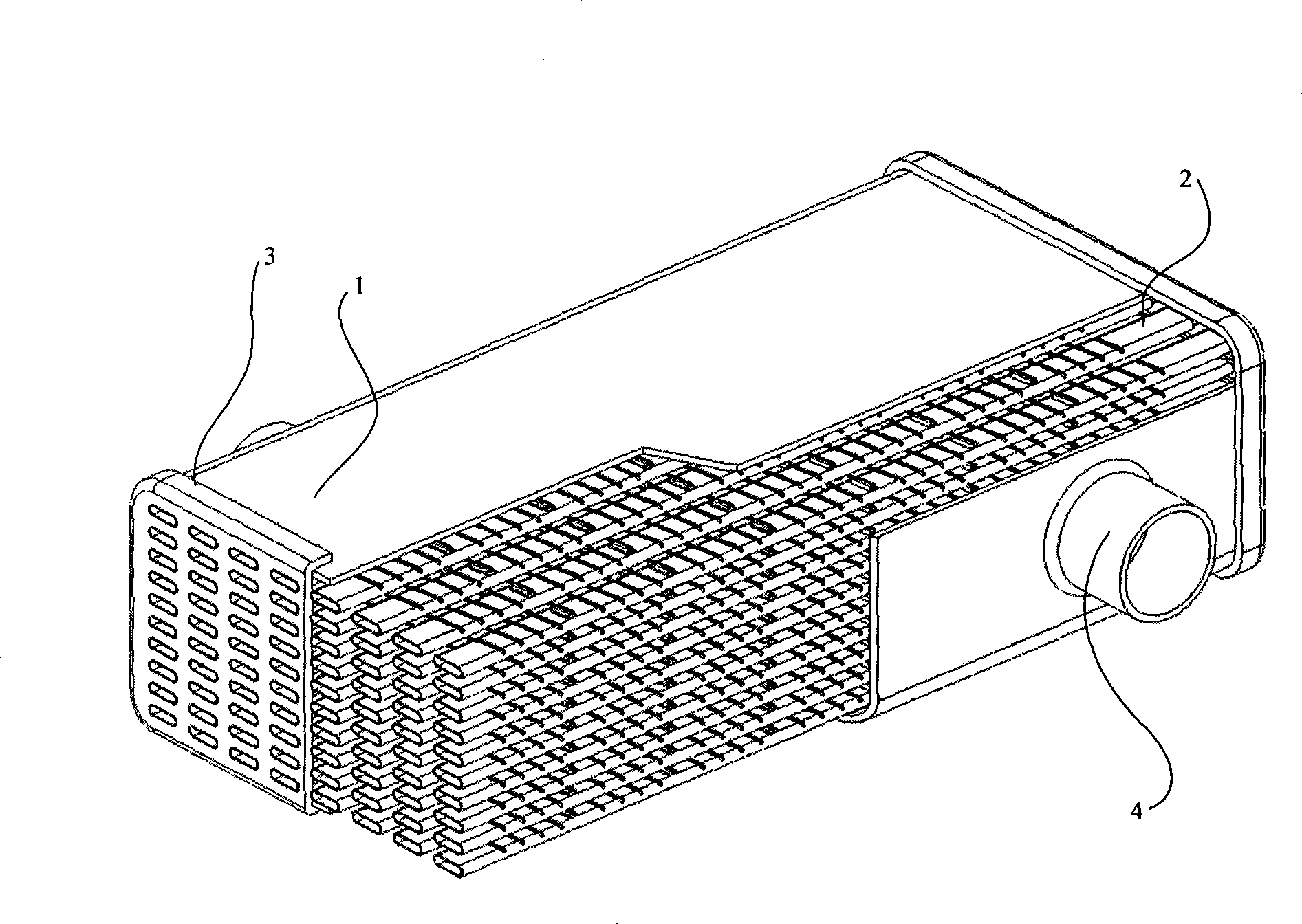
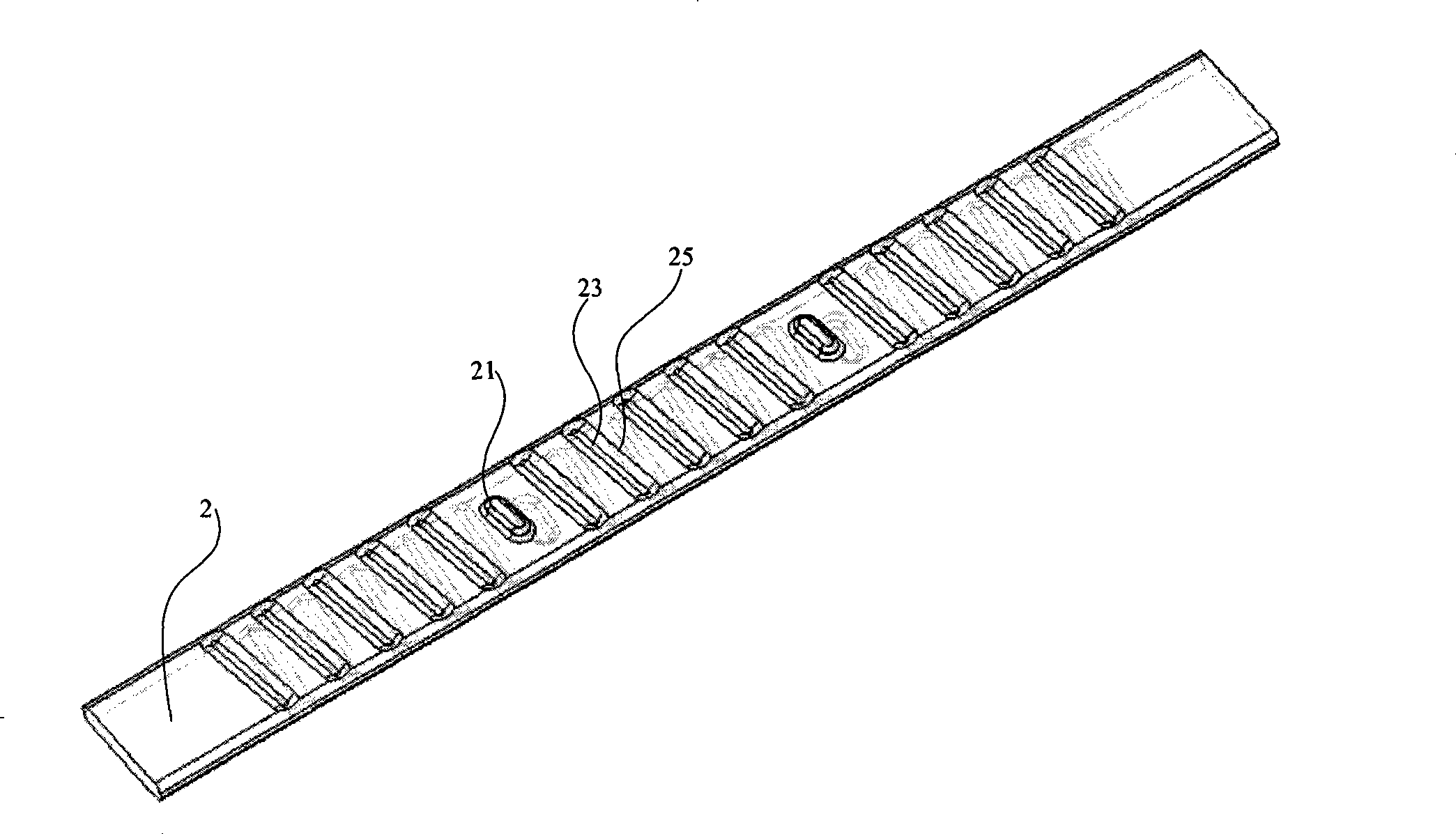
The invention discloses a flat groove heat exchange tube and a heat exchanger using the heat exchange tube. The heat exchanger is applied to an automobile engine waste gas recycling system as an engine waste gas recycling cooler and comprises a section-shaped stainless steel tube body with unequal height and width. The upper surfaces and lower surfaces of the tube body are provided with internally concave short grooves which are parallelly arranged and the upper surfaces and lower surfaces among a plurality of grooves are provided with bulges protruding externally. By the combination of the grooves and the bulges of the flat groove heat exchange tube, the heat exchange tube does not easily deform and generates stable heat exchange effect when bearing fierce temperature and pressure change. The short grooves for increasing the heat exchange efficiency can increase the strength of a plane in the long axis direction of the flat tube, inhibit deformation, and the mutual support of the bulges among the tubes forcefully improves the stress condition on the tube wall; thus leading to the minimum deformation of the flat tube, sparing an enough space among the tubes in spite of deformationand being beneficial to the flow of a medium outside the tubes.
Description
Flat grooved heat exchange tube and heat exchanger using flat grooved heat exchange tube technical field The flat grooved heat exchange tube and the heat exchanger using the flat grooved heat exchange tube of the present invention are an accessory used for an automobile engine, and an exhaust gas recirculation cooling system used in an exhaust gas recirculation system of an automobile engine. The heat exchanger of the device. Background technique The application of heat exchanger has a long history, but it is still in continuous improvement and development. Heat exchangers account for 40% to 60% of all process equipment investment in petrochemical, machinery manufacturing, oil refining, metallurgy, light industry, pharmaceutical, food and other industries, so new heat exchangers continue to emerge with the advancement of science and technology . In the field of automobiles, coolers for engine exhaust gas recirculation cooling systems are also being continuously improved ...
Claims
Login to View More Application Information
Patent Timeline
 Patent Type & Authority Patents(China)
IPC IPC(8): F28F1/12F28F1/02F28D7/10F02M25/07F02M26/29F02M26/32
CPCY02T10/121Y02T10/12
Inventor 景建周沈董浩汤俊洁
Owner BEIJING U BRIDGE CHAOYANG
Features
- R&D
- Intellectual Property
- Life Sciences
- Materials
- Tech Scout
- Unparalleled Data Quality
- Higher Quality Content
- 60% Fewer Hallucinations
Learn More Browse by: Latest US Patents, China's latest patents, Technical Efficacy Thesaurus, Application Domain, Technology Topic, Popular Technical Reports.
© 2025 PatSnap. All rights reserved.Legal|Privacy policy|Modern Slavery Act Transparency Statement|Sitemap|About US| Contact US: help@patsnap.com


