
Sanding head straight reciprocating motion apparatus for sander

A reciprocating linear motion, sanding machine technology, applied in the field of sanding machines, can solve problems such as waste, inappropriateness, and indentation on the surface of workpieces

Inactive Publication Date: 2009-04-15
张文奇
View PDF0 Cites 3 Cited by
  • Summary
  • Abstract
  • Description
  • Claims
  • Application Information

AI Technical Summary

Problems solved by technology

The previous patent case does have the disadvantages of improving the bulletin No. 25288, but the two sanding rods are not parallel to each other and move in a straight line, the stroke is greatly limited, and the workpiece will move in one direction, causing the pressure roller to be strong. Pressing the workpiece will cause obvious indentation on the surface of the workpiece. In addition, the sanding effect on the left and right sides of the workpiece is not yet optimal.
Even the combination of the No. 263813 patent and the No. 535689 "roller swing structure of the belt machine" is still not enough for relevant users to implement efficiently. The reason is that it is used for sanding. The second roller cannot be adjusted in height under the configuration of the swing structure, so that the second roller cannot be replaced separately, but must be replaced together, which is quite wasteful and uneconomical, because the first roller is mostly used for coarse sanding, and the second The roller is used for fine sanding, and the wear conditions of the two rollers are completely different. If one of the rollers is completely worn out, it is obviously very inappropriate and uneconomical to replace them together. More importantly, the second roller cannot be used at all. It can be adjusted elastically to the desired sanding height, so it is not practical

Method used


Image

  • Sanding head straight reciprocating motion apparatus for sander
  • Sanding head straight reciprocating motion apparatus for sander
  • Sanding head straight reciprocating motion apparatus for sander

Examples


Embodiment Construction

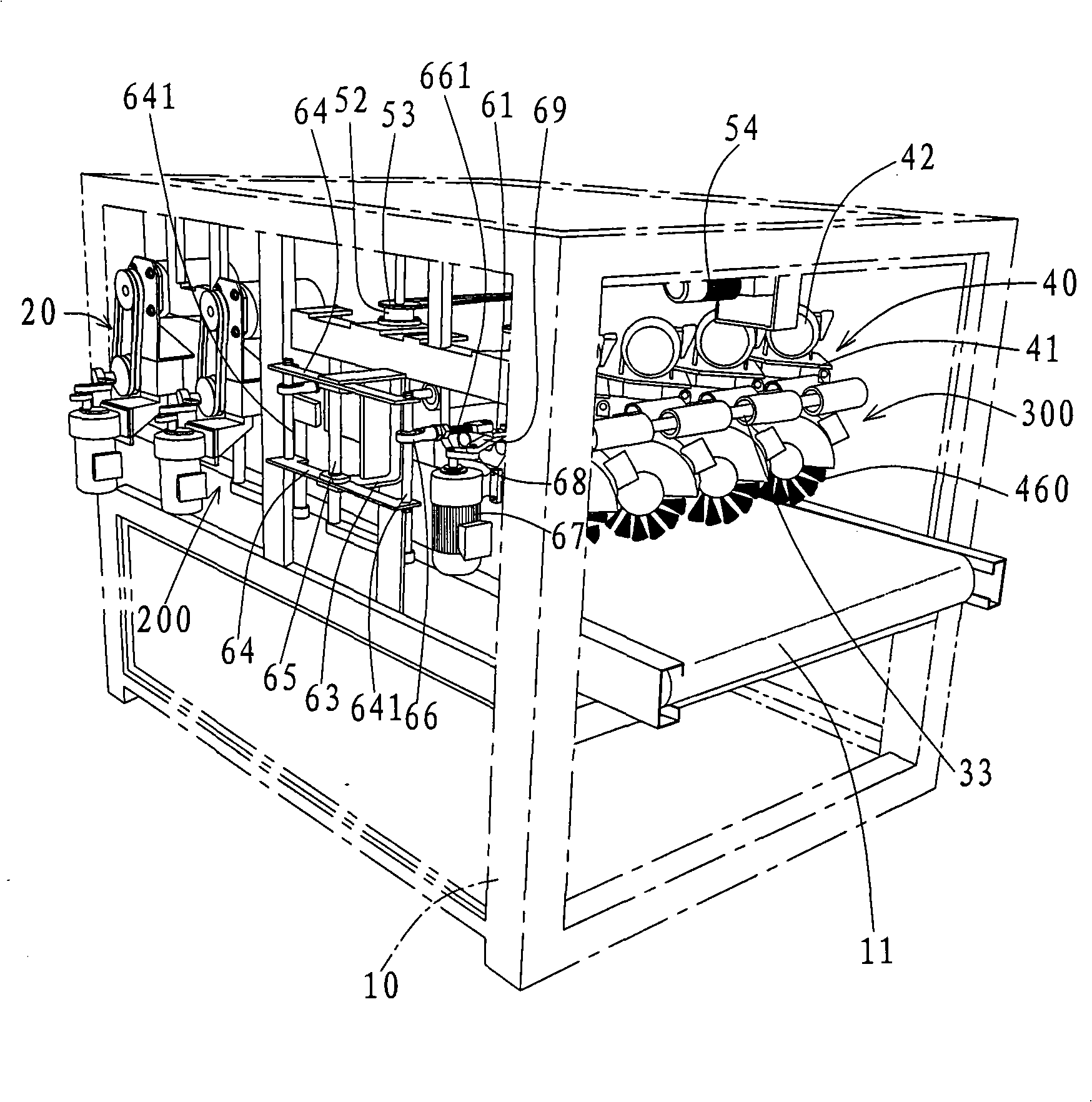
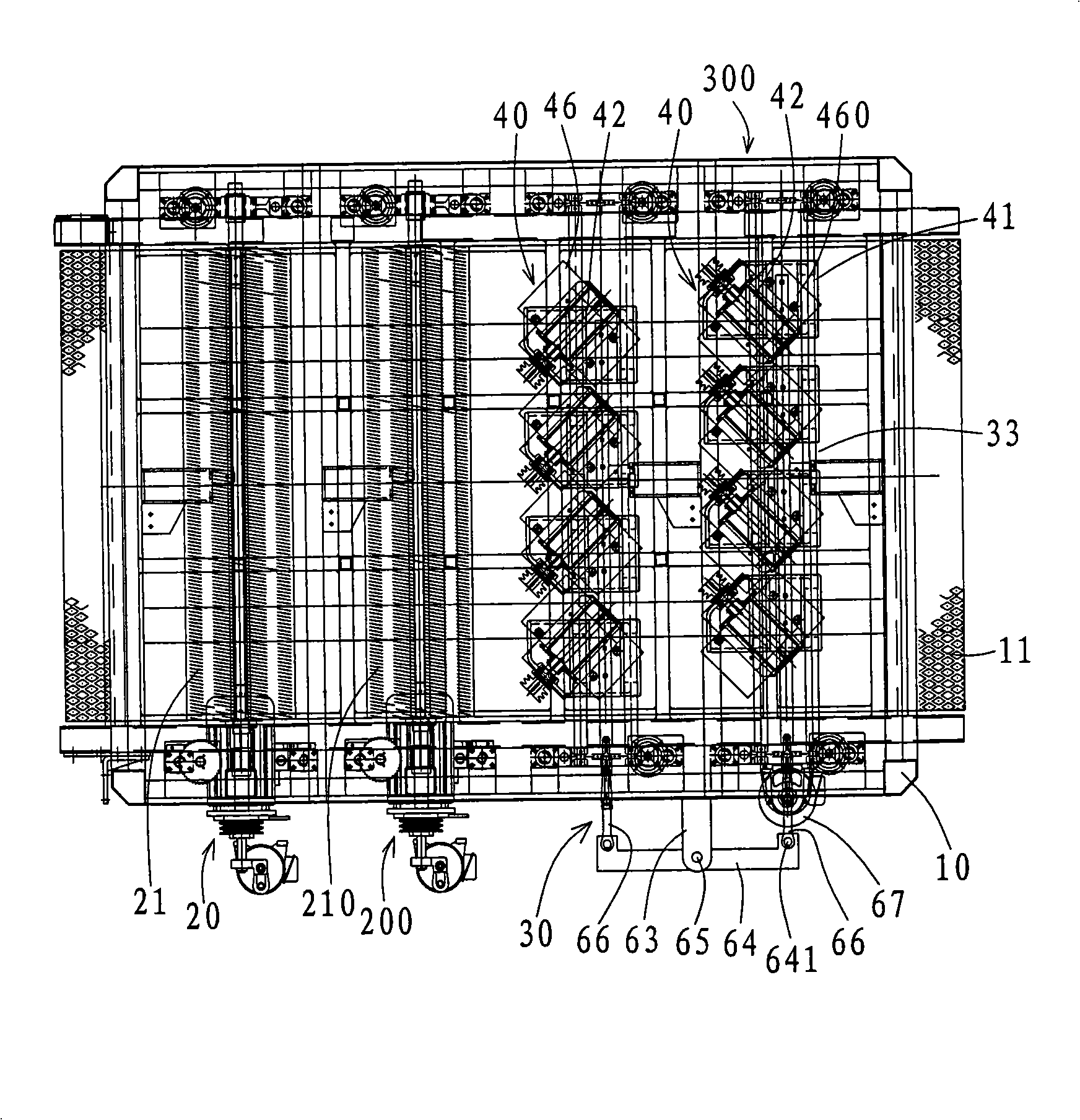
[0048] refer to Figure 1 to Figure 3 As shown, the present invention includes:

[0049] A chassis 10, a conveyor belt 11 horizontally wound around the front and back of the chassis 10, a first and second set of sanding devices 20, 200 and a third and fourth set of sanding devices 30 across the top of the conveyor belt 11, constituted by 300;

[0050] Its first and second groups of sanding devices 20, 200 are pivotally provided with a sanding element driven by a rotating shaft at the pivot above the front half of the conveyor belt 11 of the cabinet 10, and the sanding element can be an emery cloth silk wheel 21, 210, and make the first and second groups of sanding devices 20,200 controlled by a lifting transmission device that is respectively arranged, so that the two emery cloth wire wheels 21 and 210 can be engaged in height adjustment respectively, and the first and second groups of sanding devices 20 , 200 and control the displacement of the first and second groups of sa...


PUM


Abstract

The invention relates to a linear reciprocating device for a sanding head of a sander. A case is provided with two groups of sanding devices at intervals in front and back, the two groups of the sanding devices are provided with a sanding element capable of sanding respectively, a linkage device is arranged between the two groups of the sanding devices, the linkage device uses a shaft element to be pivoted with the center of a rocking lever to the case, one end of the rocking lever is linked with one group of the sanding devices, the other end of the rocking lever is linked with the other group of the sanding devices, and the linkage device uses a driving structure to apply a torque on the rocking lever, so that the rocking lever can do reciprocating circular motion within a limited angle by using the shaft element as a supporting point; and further the two groups of the sanding devices can do sanding work of mutually parallel and symmetrically cross reciprocating linear motion without interference.

Description

technical field [0001] The invention relates to the field of sanding machines, in particular to a reciprocating linear motion device for a sanding head of a sanding machine. Under the technology of reciprocating linear motion, rotary motion and individual lifting compensation height at the same time. Background technique [0002] As shown in Taiwan Patent Publication No. 25288 "Abrasive Cloth Silk Wheel", it cuts the abrasive cloth into strips of appropriate size, and makes the sand-containing surface outward, and then combines the abrasive cloth threads together on a shaft. And arranged in a dense wheel shape, so that the end face of the emery cloth can be used for sanding. [0003] It is mainly equipped with a conveyor belt under the abrasive cloth wire wheel, and the wood workpiece is sent through the abrasive cloth wire wheel by the conveyor belt for processing. Generally speaking, the rotating sanding direction of the end surface of the abrasive cloth wire is parallel ...

Claims


Application Information

Patent Timeline
IPC IPC(8): B24B47/12
Inventor 张文奇
Owner 张文奇
Learn More