Wing with high intensity and high stiffness

A high-stiffness, high-strength technology applied to wings. In this field, it can solve the problems of uncoordinated deformation of the wing handle and the wing, low machining efficiency of the wing handle, poor stiffness and strength of the wing, etc., and achieve the effect of low manufacturing technology requirements, coordinated deformation, and avoiding instability and warping

Inactive Publication Date: 2009-03-11
HARBIN FRP INST
View PDF0 Cites 5 Cited by
  • Summary
  • Abstract
  • Description
  • Claims
  • Application Information

AI Technical Summary

Problems solved by technology

[0004] The purpose of the present invention is to solve the problem that the upper and lower skins of the existing fins have poor overall rigidity and strength due to the discontinuity of fibers, local instability and warping of the fins are easy to occur, and the bearing strength of the wing shank is low. The problems of incongruous deformation between the fins and the low efficiency of machining of the wing shank, thus providing a wing with high strength and high rigidity

Method used


Image

  • Wing with high intensity and high stiffness
  • Wing with high intensity and high stiffness
  • Wing with high intensity and high stiffness

Examples


specific Embodiment approach 1

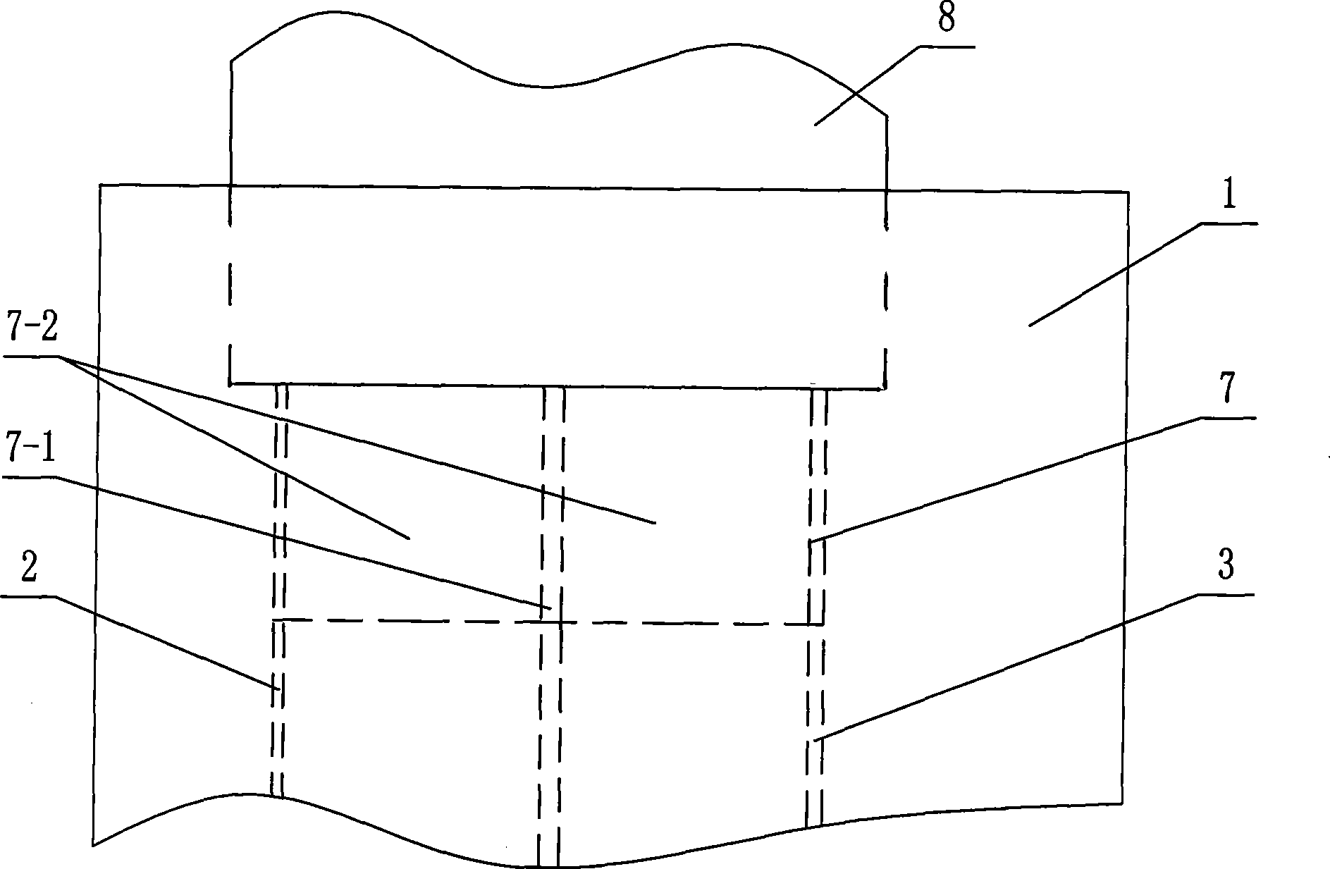
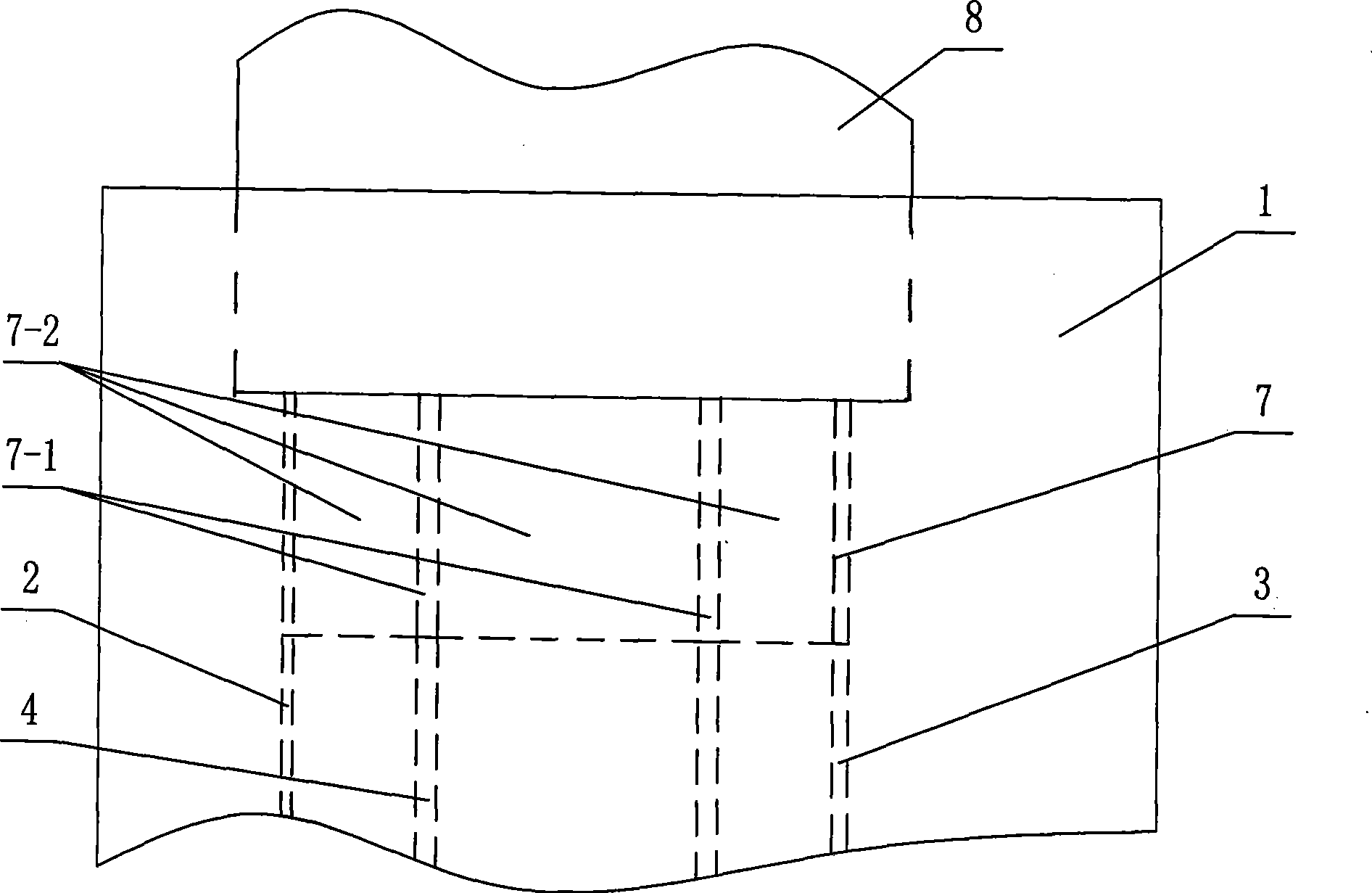
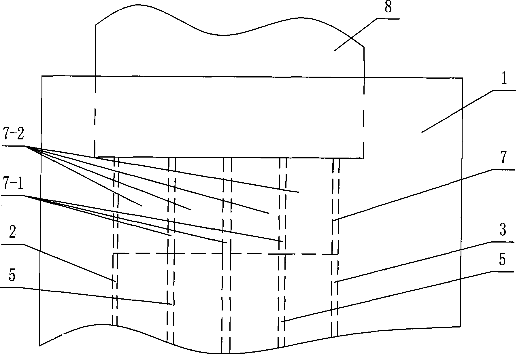
[0010] Specific implementation mode one: combine figure 1 , Figure 4 and Figure 7 Describe this embodiment, this embodiment is made up of fin and metal wing handle, and described fin is made up of composite material skin 1, first core pipe 2 and second core pipe 3, and the vertical of described first core pipe 2 The straight face is affixed to the vertical surface of the second core pipe 3 to form a reinforcement body, and the composite skin 1 is coated on the outer wall of the reinforcement body formed by the first core pipe 2 and the second core pipe 3, so The metal wing handle is composed of a first-level step 7 and a second-level step 8, and the first-level step 7 and the second-level step 8 are integrated from bottom to top to form a two-step variable-section structure. There is a notch 7-1 on the step 7 to form two cores 7-2, and the two cores 7-2 of the first step 7 are respectively inserted into the first core tube 2 and the second core tube 3 Inside.

specific Embodiment approach 2

[0011] Specific implementation mode two: combination Figure 4 The present embodiment will be described. The width W of the cross-section of the fin of the present embodiment is 150 mm to 250 mm, and the thickness H is 20 mm to 30 mm. Such setting can more effectively avoid local instability and warping of the fins. Other compositions and connections are the same as in the first embodiment.

specific Embodiment approach 3

[0012] Specific implementation mode three: combination Figure 4 The present embodiment will be described. The composite material skin 1 of the present embodiment is a fiber-reinforced resin-based composite material skin. With such arrangement, the overall stiffness and strength of the fins are better. Other compositions and connections are the same as in the first embodiment.


PUM

PropertyMeasurementUnit
Widthaaaaaaaaaa
Thicknessaaaaaaaaaa
Widthaaaaaaaaaa

Abstract

The invention relates to a wing, in particular to a wing with high strength and high rigidity. The invention solves the problems that the whole rigidity and strength of the wing are bad due to non-continuous fiber of the upper envelope and lower envelope of the existing wing, the wing is easy to generate local destabilization and warpage, the wing handle has low bearing strength, the deformation of the wing handle and the wing is not harmonized, and the mechanical processing efficiency of the wing handle is low. The wing comprises three proposals: proposal 1, the envelope is covered on the external wall of the reinforced rib formed by a first core pipe and a second core pipe; two cores are respectively inserted inside the first core pipe and the second core pipe; proposal 2, the envelope is covered on the external wall of the reinforced rib formed by a first core pipe, a second core pipe and a third core pipe; three cores are respectively inserted inside the first core pipe, the second core pipe and the third core pipe; proposal 3, the envelope is covered on the external wall of the reinforced rib formed by a first core pipe, a second core pipe and two fourth core pipes; four cores are respectively inserted inside the first core pipe, the second core pipe and two fourth core pipes; the wing has good whole rigidity and strength and high bearing strength.

Description

technical field [0001] The present invention relates to a wing. Background technique [0002] Composite materials are the material basis of high-performance products and an important guarantee for the realization of advanced designs. Compared with other materials, composite materials have high specific strength and specific stiffness. Under the trend of full composite materials for wings at home and abroad, According to the development plan of different specifications and types of airfoils in China, for the airfoils with large aspect ratio and thin wings, the wingspan is large, the airfoil is thin, and the chord length is small. In order to prevent the large deformation of the airfoil from damage, the structure of the airfoil To have relatively high strength and rigidity. The first structure of the existing fiber-reinforced resin-based composite airfoil adopts the structural form of upper skin, lower skin and internal vertical and horizontal ribs. The upper skin, lower skin...

Claims


Application Information

Patent Timeline
IPC IPC(8): B64C3/26
Inventor 路明坤梁岩石建军韩丽华曲艳双杨永生
Owner HARBIN FRP INST
Why Eureka
Try Eureka