Heat exchanger for vehicle
A technology for heat exchangers and vehicles, applied in the direction of heat exchanger types, heat exchanger shells, indirect heat exchangers, etc., can solve problems such as no function, poor heat exchange efficiency, insufficient circulation of cooling air, etc., and achieve improved The effect of cooling performance
- Summary
- Abstract
- Description
- Claims
- Application Information
AI Technical Summary
Problems solved by technology
Method used
Image

Examples
Embodiment 1
[0061] Next, Example 1 will be described.
[0062] In addition, the vehicle front-rear direction and the vehicle width direction will be described as the front-rear direction and the left-right direction.
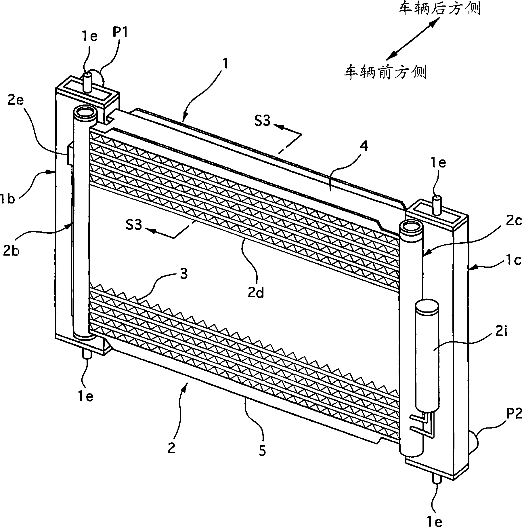
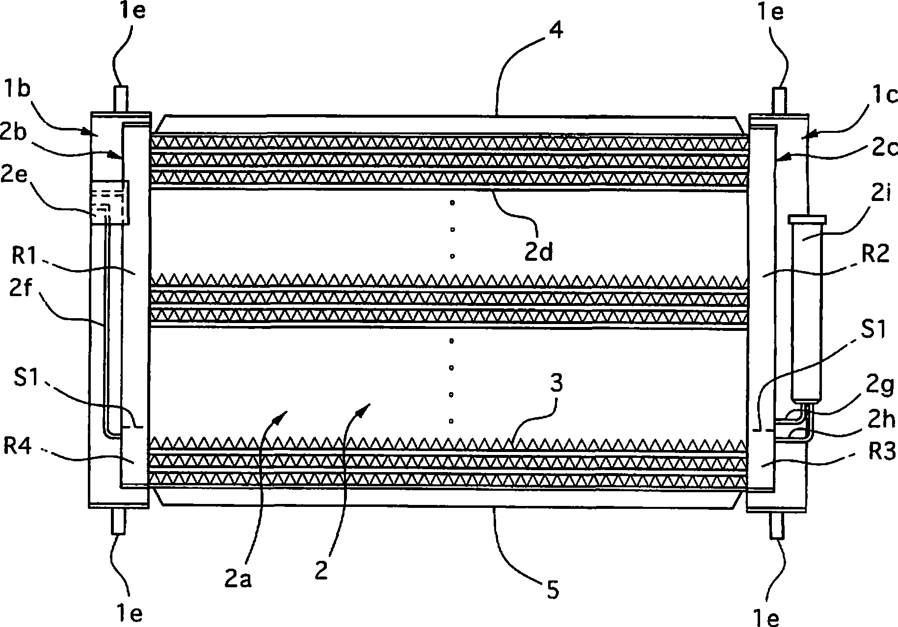
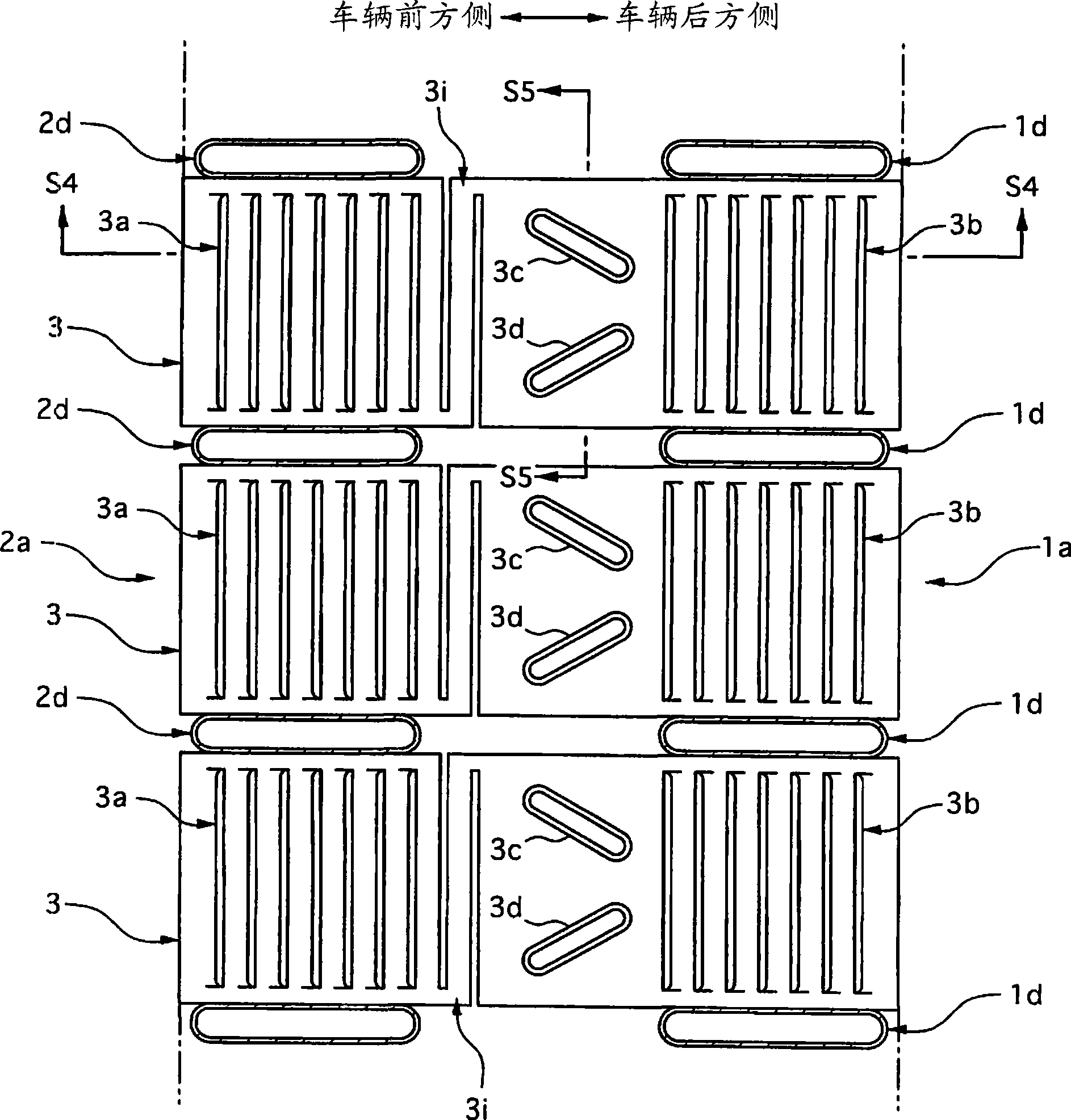
[0063] figure 1 is a perspective view of a vehicle heat exchanger according to Embodiment 1 of the present invention, figure 2 is a front view of the above vehicle heat exchanger, image 3 yes figure 1 The end view of S3-S3 is a diagram explaining the core.
[0064] Figure 4 yes image 3 End view of S4-S4, Figure 5 yes image 3 The end view of S5-S5, Fig. 6 is the perspective view of the corrugated fin test model of present embodiment 1, Figure 7 It is a figure explaining the recessed part and heat insulation part of this Example 1, Figure 8 , 9 It is a figure explaining the function.
[0065] Figure 10-16 It is a perspective view of the test model of the corrugated fins A1-A7 used as the comparison object of the corrugated fin of this Example 1, and FIG. ...
Embodiment 2
[0105] Next, Example 2 will be described.
[0106] In this second embodiment, the same reference numerals are assigned to the same components as those in the above-mentioned first embodiment, their descriptions are omitted, and only the differences will be described in detail.
[0107] Figure 18 It is a figure explaining the corrugated fin of Example 2 of this invention, Figure 19 yes Figure 18 The cross-sectional view of S19-S19 is a diagram for explaining the function.
[0108] Such as Figure 18 As shown, in the present embodiment 2, there are the following differences with the embodiment 1: the core portion 1a of the radiator 1 is equipped with a separate corrugated fin 20, and the corrugated fins of the core portion 1a of the radiator 1 20 is formed to protrude from the core portion 1a toward the upstream side of the cooling air, and the first protruding portion 21 and the second protruding portion 22 arranged in an approximately inverted “H” shape with respect to ...
Embodiment 3
[0117] Next, Example 3 will be described.
[0118] In this third embodiment, the same reference numerals are assigned to the same components as those in the above-mentioned second embodiment, their descriptions are omitted, and only the differences will be described in detail.
[0119] Figure 20 It is a figure explaining the corrugated fin of Example 3 of this invention, Figure 21 yes Figure 20 Cutaway view of the S21-S21, Figure 22 , 23 It is a perspective view explaining the fixing structure of the radiator and the condenser.
[0120] Such as Figure 20 , 21 As shown, in this embodiment 3, there is the following difference with embodiment 2: except that the radiator 1 has corrugated fins 30, the core 2a of the condenser 2 is also equipped with a separate corrugated fin 30 In this case, the corrugated fins 30 of the core 2a of the condenser 2 protrude from the core 2a to the downstream side of the cooling air, and the end 30a is arranged adjacent to the end 20a of ...
PUM
 Abstract
Description
Claims
Application Information
 - R&D
- Intellectual Property
- Life Sciences
- Materials
- Tech Scout
- Unparalleled Data Quality
- Higher Quality Content
- 60% Fewer Hallucinations
Browse by: Latest US Patents, China's latest patents, Technical Efficacy Thesaurus, Application Domain, Technology Topic, Popular Technical Reports.
© 2025 PatSnap. All rights reserved.Legal|Privacy policy|Modern Slavery Act Transparency Statement|Sitemap|About US| Contact US: help@patsnap.com