
Tube stand of backlight module

A technology for backlight modules and lamp tubes, applied in optics, light source fixation, nonlinear optics, etc., can solve problems such as inconvenient assembly of backlight modules, breaking force arms, and component damage

Active Publication Date: 2009-02-11
AU OPTRONICS CORP
View PDF0 Cites 11 Cited by
  • Summary
  • Abstract
  • Description
  • Claims
  • Application Information

AI Technical Summary

Problems solved by technology

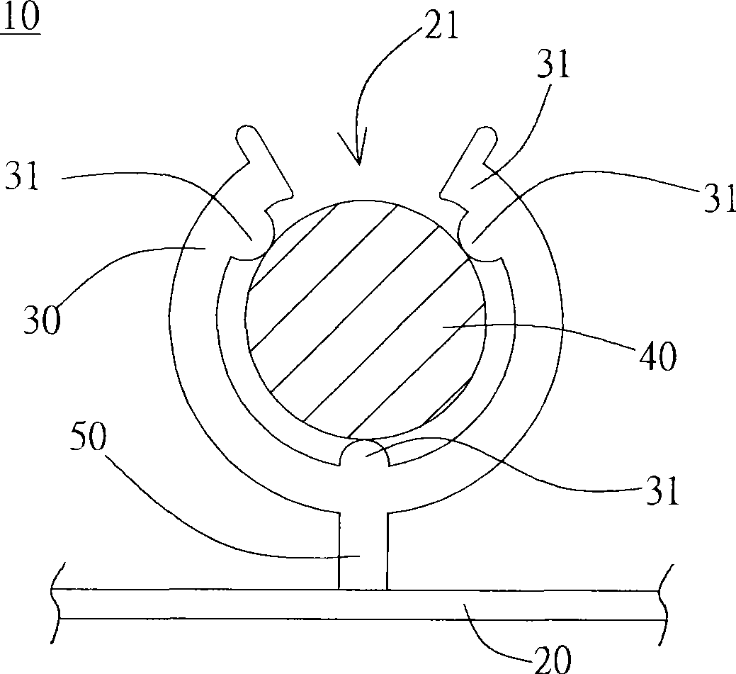
Therefore, if the opening between the force arms is much smaller than the lamp tube, improper assembly and application of force may cause cracks or deformation of the force arms when the lamp tube is engaged.
[0006] The above situations will cause inconvenience in the assembly of the backlight module and damage to the components, resulting in increased assembly man-hours and production costs, and may reduce the life of the lamp tube, resulting in poor product quality

Method used


Image

  • Tube stand of backlight module
  • Tube stand of backlight module
  • Tube stand of backlight module

Examples


Embodiment Construction

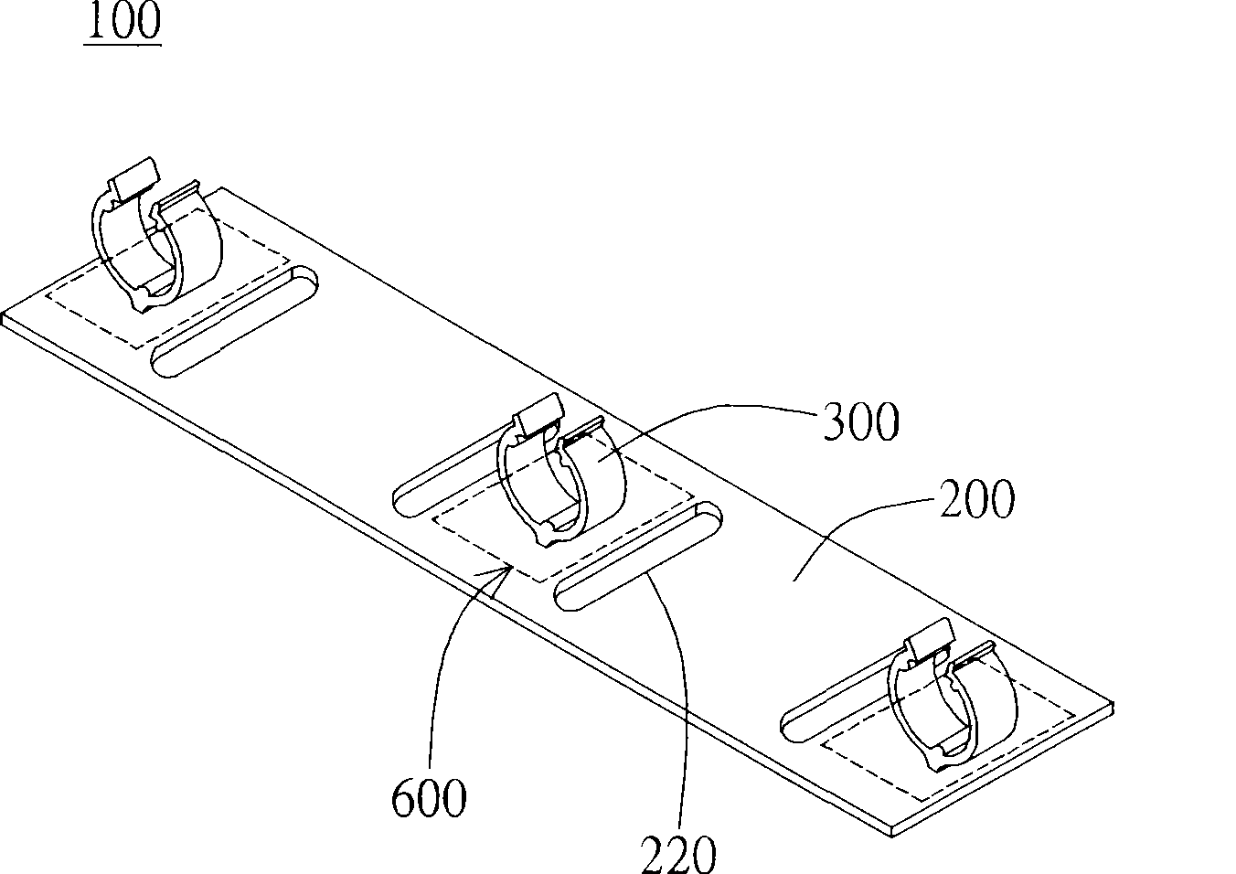
[0040] Such as Figure 2a In the illustrated embodiment, the backlight module lamp holder 100 of the present invention includes a base 200 and a lamp clamping portion 300, wherein the base 200 has a hollowed-out gap 220 and a connection area 600 (shown as a dotted line), wherein the hollowed-out gap 220 Adjacent to the connection area 600. The lamp holder 300 is disposed on the base 200 and in the connection area 600 of the base. Among them, the base 200 is made of a flexible material, such as polycarbonate (PC), acrylonitrilebutadiene styrene (ABS), polypropylene (PP), polyterephthalene Polyethylene terephthalate (PET), polymethylmethacrylate (PMMA), polylactic acid (PLA) or mixtures thereof. The lamp holder 300 is made of polymer, metal, metal alloy or metal compound. However, the flexible material of the aforementioned base 200 is not limited to this.

[0041] Such as Figure 2a In the preferred embodiment shown, the hollowed-out gap 220 on the base 200 is located on the side o...


PUM


Abstract

The invention discloses a lamp tube bracket of a backlight module to support lamp tubes, which comprises a base and a lamp tube clamping part arranged on the base. Hollow-out gaps are formed on the base and are arranged at the side of the lamp tube clamping part. The connecting area between the lamp tube clamping part and the base has elasticity, which allows the lamp tube clamping part to displace corresponding to the base.

Description

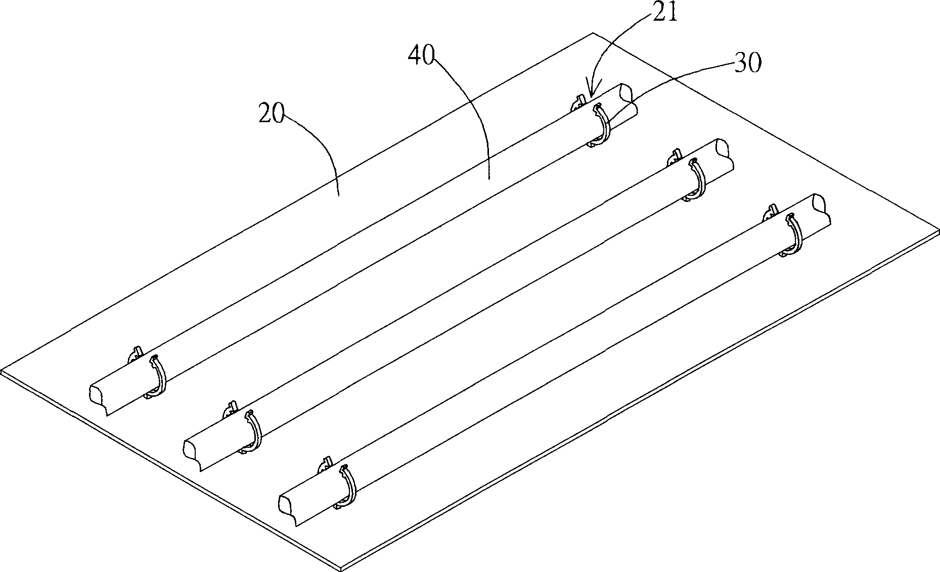
Technical field [0001] The invention relates to a backlight module lamp tube bracket; in particular, it relates to a backlight module lamp tube bracket for a liquid crystal display. Background technique [0002] In recent years, liquid crystal displays (Liquid Crystal Display) have become the mainstream of various display devices. For example, household televisions, personal computers and laptop computer monitors, mobile phones and digital cameras are all products that use liquid crystal display devices in large quantities. Among them, a backlight module applied to a liquid crystal display device is used to supply a light source with sufficient brightness and uniform distribution of the liquid crystal so that the liquid crystal display device can display images normally. Backlight modules can be divided into edge-lighting backlight modules and bottom-lighting backlight modules, each of which is suitable for liquid crystal panels of different sizes. [0003] Figure 1a and Figure...

Claims


Application Information

Patent Timeline
Patent Type & Authority Applications(China)
IPC IPC(8): F21V15/04F21V21/00F21V19/00G02F1/13357G02F1/1335
Inventor 吴有章林信吾柯雅华
Owner AU OPTRONICS CORP
Learn More