
Accessories mill-head bank

A technology of milling head and accessories, which is applied in the direction of metal processing machinery parts, clamping, support, etc., can solve the problems of low production efficiency, and achieve the effects of low design and manufacturing costs, simple program setting, and less design workload

Active Publication Date: 2009-02-11
JIER MACHINE TOOL GROUP
View PDF0 Cites 9 Cited by
  • Summary
  • Abstract
  • Description
  • Claims
  • Application Information

AI Technical Summary

Problems solved by technology

[0003] In order to overcome the defect that the current accessory milling head needs to be transported by manpower, which makes the production efficiency low, the present invention provides an accessory milling head library that can automatically transport the accessory milling head according to the numerical control command

Method used


Image

  • Accessories mill-head bank
  • Accessories mill-head bank
  • Accessories mill-head bank

Examples


Embodiment 1

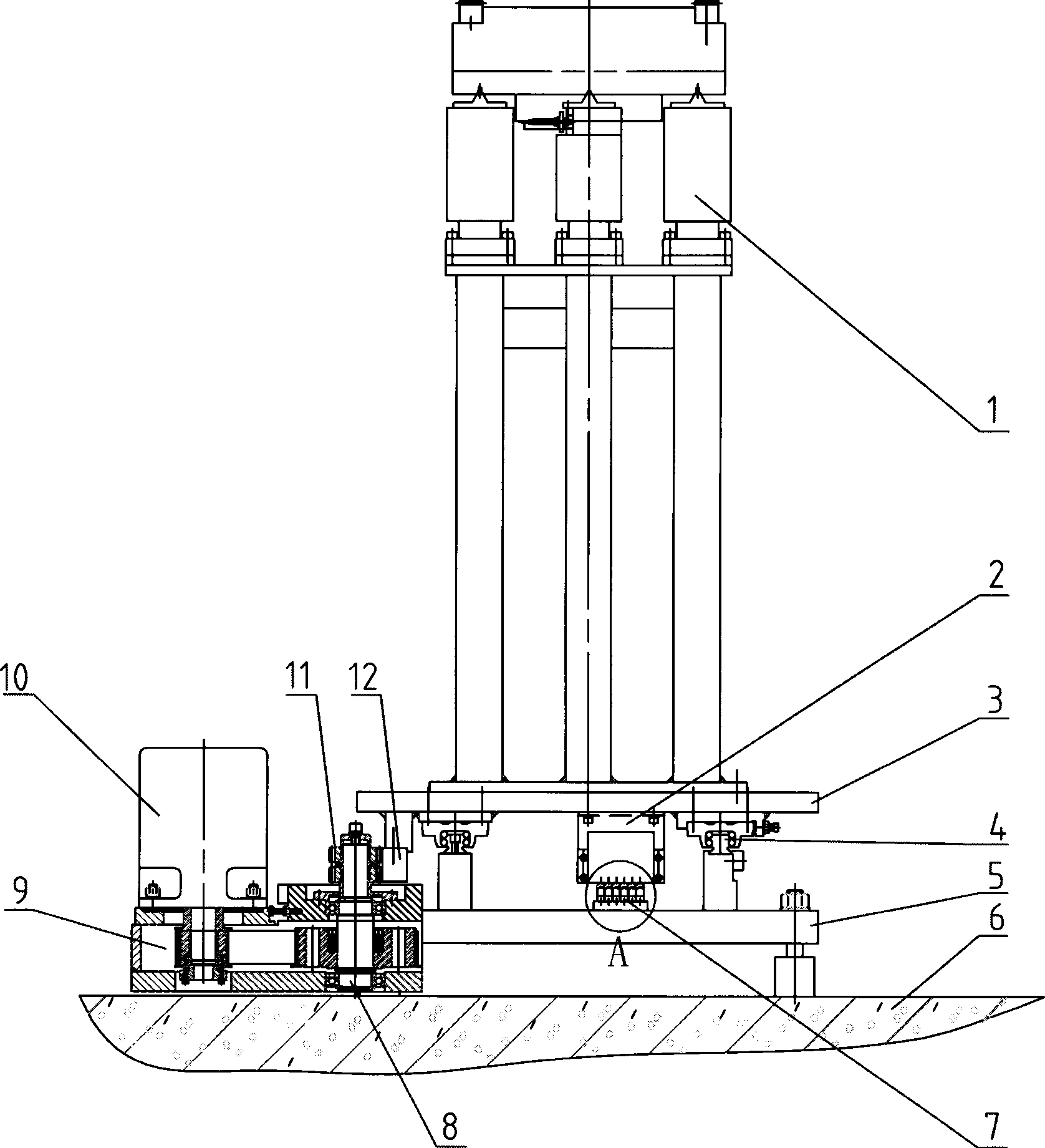
[0020] Refer to the manual attached figure 1 To 5, the accessory milling head library of this embodiment includes four accessory milling heads 1, and also includes a support 5 fixed on the foundation and a guide rail pair 4 on the upper part of the support for carrying the accessory milling head. head slide 3; and

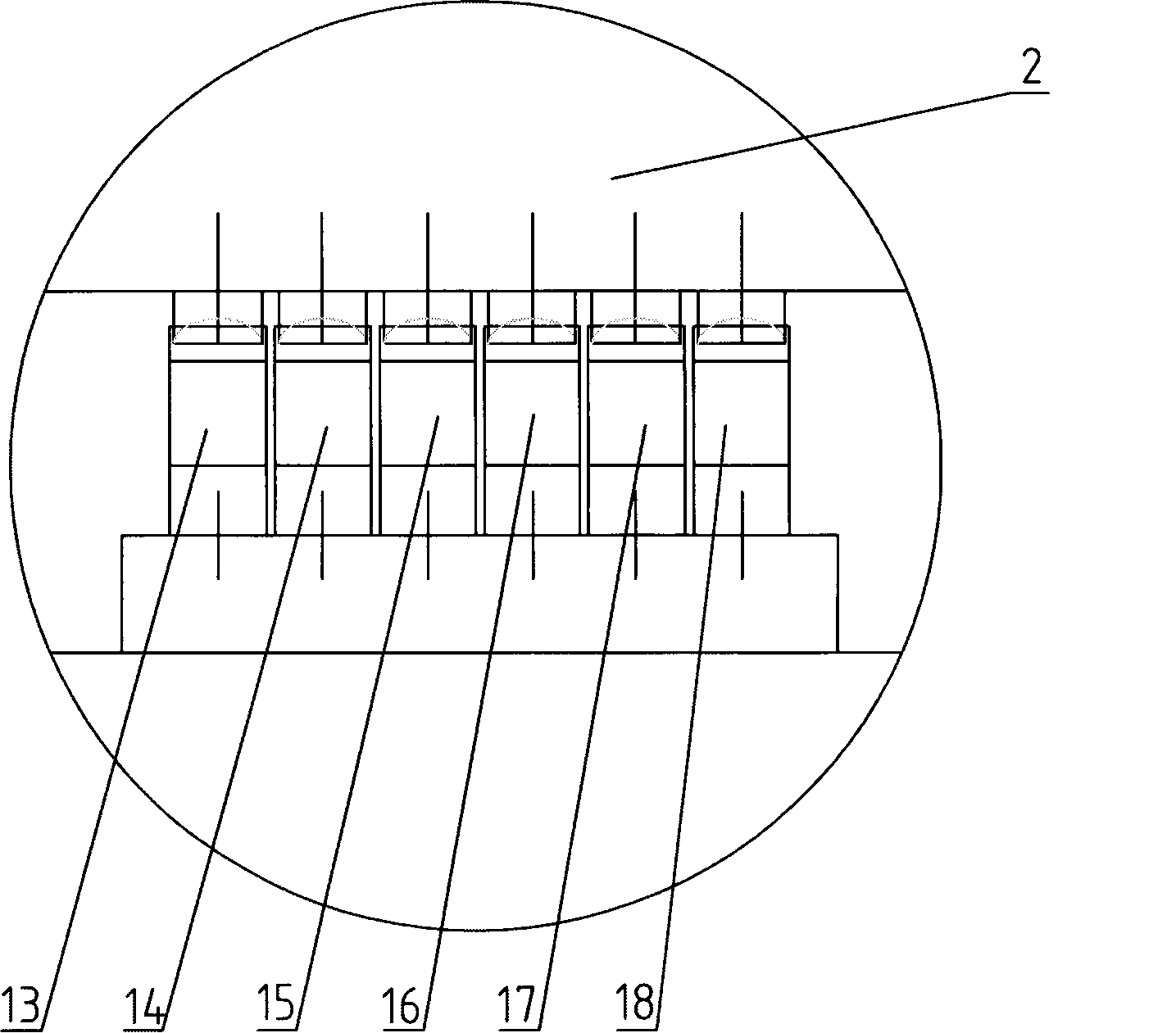
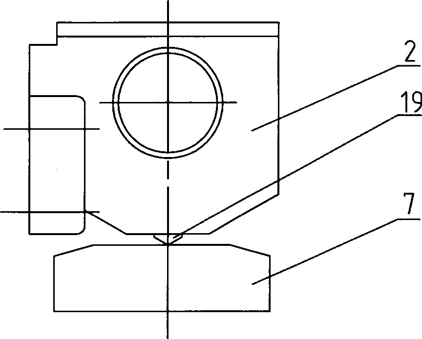
[0021] A combination switch 2 is arranged on the lower side of the tail of the sliding table, its switches are evenly distributed horizontally, and the guide rod 19 is downward; and

[0022] The bracket 7 is arranged on the upper side of the support for triggering the combination switch, and includes the attachment milling head brackets 14 , 15 , 16 , 17 distributed in the longitudinal direction corresponding to the number of the attachment milling heads. Corresponding to the distance between the attachment milling heads and one-to-one correspondence with the switches, when the attachment milling head runs to the replacement position, the corresponding switch just...

Embodiment 2

[0028] Compared with Embodiment 1, this embodiment is mainly different in the selection of the mechanical transmission device. The mechanical transmission device includes a rack 12 arranged under the sliding table 3, and an output shaft gear and the The gear box is meshed with the rack, the input shaft of the gear box is connected to the motor 10, and the gear box is used as an intermediate reduction transmission device, which is convenient for installation.

[0029] For the selection of the number of switches for the switch and the combination switch, the main consideration is the number of attachment milling heads.


PUM


Abstract

The invention discloses an accessory milling head base. The accessory milling head base comprises at least one accessory milling head, and also comprises a support fixed on the base and a slide platform matched with the support through an upper guide pair for bearing the accessory milling head; a combined switch which is arranged on the lower side of the tail of the slide platform, the switch is transversally and uniformly distributed, and guide bar arranged downward; actuators which are arranged on the upper side of the support for triggering the combined switch, the actuators comprise longitudinally distributed accessory milling head actuators with the quantity corresponding to the quantity of the accessory milling head, the spacing of the actuators corresponds to the spacing of the accessory milling heads, the actuators correspond to the switch, and when the accessory milling heads is moved to the replacing position, the corresponding switch is triggered by the corresponding actuator; and a motor which is used for driving the slide platform through a mechanical drive unit. The invention provides an accessory milling head base which can realize automatic conveying of the accessory milling heads according to a numerical control command.

Description

(1) Technical field [0001] The invention relates to an accessory milling head library, in particular to an accessory milling head library for conveying the accessory milling head by means of a linear guide rail. (2) Background technology [0002] Gantry machining centers and CNC gantry boring and milling machines belong to the category of large and heavy machine tools, which are suitable for the processing of large and medium-sized parts in machinery, steel, energy, automobiles, aerospace, weapons, ships and other industries. In order to meet the processing needs of different workpieces, CNC machine tools are equipped with a variety of attachment milling heads. The attachment milling head library can be established to expand the processing range. However, the replacement part of the current attachment milling head needs to be done manually. The attachment milling head library There is a guide rail on which multiple sets of trolleys for placing the attachment milling head are...

Claims


Application Information

Patent Timeline
Patent Type & Authority Applications(China)
IPC IPC(8): B23Q3/157
Inventor 梁秋娜武彩琳
Owner JIER MACHINE TOOL GROUP
Learn More