
Motor controller

A control device, motor technology, applied in the direction of motor control, AC motor control, motor generator control, etc.

Inactive Publication Date: 2009-02-04
HONDA MOTOR CO LTD
View PDF2 Cites 14 Cited by
  • Summary
  • Abstract
  • Description
  • Claims
  • Application Information

AI Technical Summary

Problems solved by technology

However, in References 1 and 2, there is no description of a structure in which the motor is used in an energization method other than the traction operation when the regenerative operation of the axial gap type motor is performed.

Method used


Image

  • Motor controller
  • Motor controller
  • Motor controller

Examples


Embodiment Construction

[0030] Reference figure 1 ~ FIG. 8 illustrates an embodiment of the present invention.

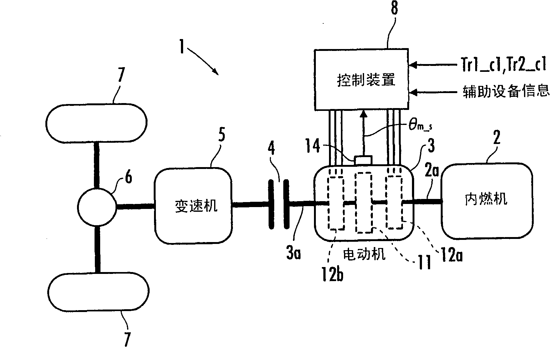
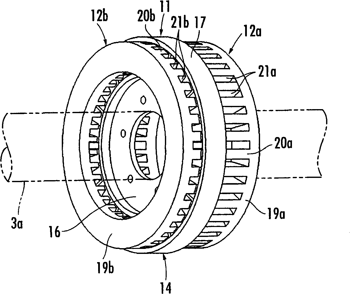
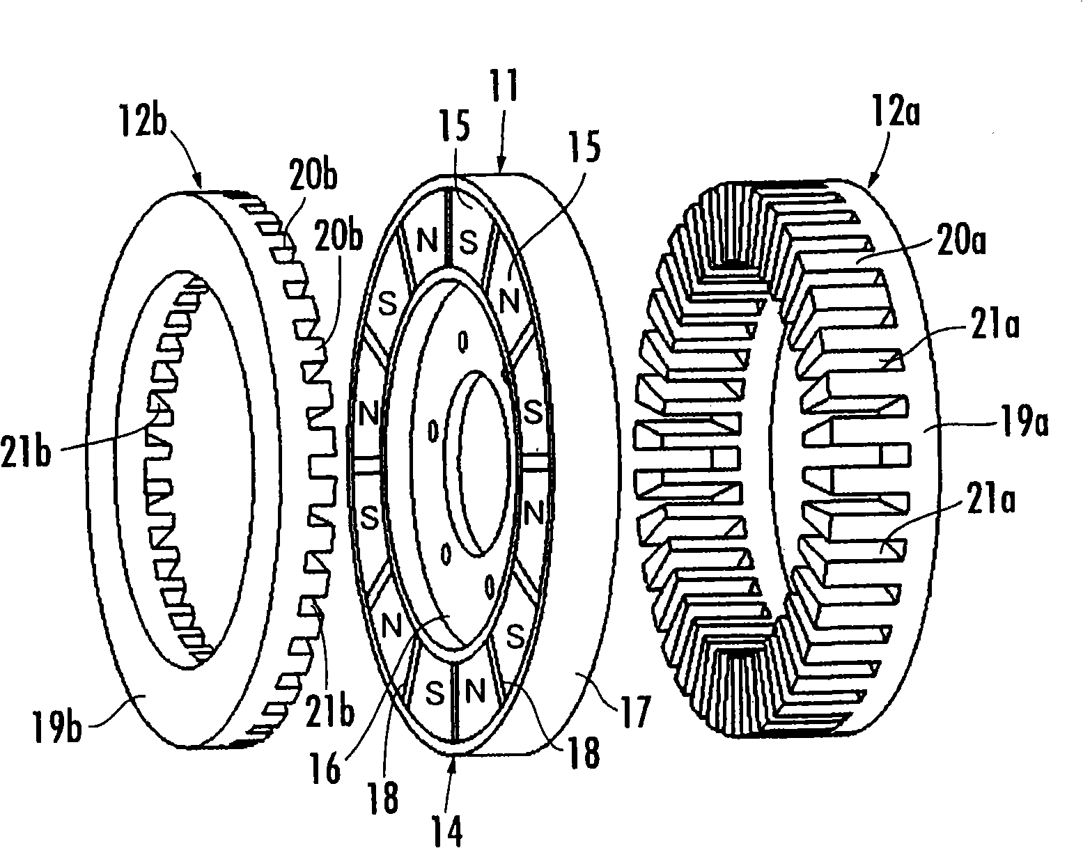
[0031] First, refer to figure 1 The general structure of a vehicle equipped with the motor control device of the present invention will be described. The vehicle 1 of the present embodiment is a parallel hybrid vehicle and has an internal combustion engine (engine) 2 as a main propulsion generating source, and an electric motor 3 as an auxiliary propulsive generating source. The electric motor 3 is an axial gap type electric motor having a rotor 11, a first stator 12a, and a second stator 12b. The electric motor 3 has a resolver 14 that detects the rotation angle of the rotor 11.

[0032] The output shaft 2a of the internal combustion engine 2 and the rotating shaft 3a that rotates integrally with the rotor 11 of the electric motor 3 are directly connected coaxially. In addition, the output shaft 2a of the internal combustion engine 2 and the rotating shaft 3a of the electric motor 3 may be ...


PUM


Abstract

A motor controller for an axial-gap motor permits a reduced size of the entire system of including a drive circuit and a power source of the motor, reduced cost, and higher reliability to be achieved by controlling the energization mode of the motor. The motor controller has a torque command determiner (50) which inputs a first DC voltage VH-s to a first inverter (32a) at least either when a rotor (11) is at a halt or when the number of revolutions delta theta m / delta t of the rotor is a predetermined number of revolutions or less, supplies a field axis current Idf for changing the magnetic flux of a field of the rotor (11) to a first stator from the first inverter such that the amount of energization is temporally changed, converts an induced voltage developed in a second stator (12b) by the supplied field axis current into a second DC voltage by a second inverter (32b), and outputs the second DC voltage, thereby charging a second battery (38b).

Description

Technical field [0001] The invention relates to a control device for an axial gap type motor. Background technique [0002] Conventionally, there has been known an axial gap type motor having a rotor with permanent magnets, two stators arranged on both sides of the rotor in the direction of the rotation axis of the rotor, and armature windings attached to each stator ( For example, refer to Japanese Patent Application Publication No. 10-271784 and Japanese Patent Application Publication No. 2001-136721). According to such an axial gap motor, while shortening the length of the motor rotor in the axial direction, relatively high output torque can be generated. [0003] In the technique described in the above-mentioned publication, the armature windings of the two stators arranged on both sides of the rotor are energized to perform energization control of the axial gap motor. And, by this, the leakage flux in the stator armature is reduced, and the output torque of the motor is incr...

Claims


Application Information

Patent Timeline
Patent Type & Authority Applications(China)
IPC IPC(8): H02P6/00H02P6/08H02K1/27H02K16/04H02K21/24H02P21/00H02P21/04H02P21/06H02P21/10H02P23/03H02P27/04
CPCH02P21/06Y02T10/7066Y02T10/643Y02T10/6226Y02T10/725H02P9/007B60L7/14H02P2207/076Y02T10/641B60L2210/20H02P2201/07Y02T10/7005B60L11/1868B60L15/007B60K6/485B60L15/025B60L7/16B60L11/14Y02T10/7077H02P2207/073B60L2220/54H02P2009/002Y02T10/70H02P2101/45B60L50/16B60L58/20Y02T10/62Y02T10/64Y02T10/72Y02T10/7072
Inventor 新博文
Owner HONDA MOTOR CO LTD
Learn More