
Switch cupboard monitoring management apparatus

A switchgear and output technology, applied in circuit devices, electrical components, etc., can solve the problems of high after-sales service costs, many additional equipment, complicated connections, etc., and achieve the effect of reducing after-sales service costs.

Inactive Publication Date: 2009-02-04
NINGBO TIANAN GRP CO LTD
View PDF1 Cites 5 Cited by
  • Summary
  • Abstract
  • Description
  • Claims
  • Application Information

AI Technical Summary

Problems solved by technology

[0002] The switchgear is a necessary equipment for power system distribution of electric energy; the switchgear currently used is mainly composed of primary equipment and secondary equipment; among them, the primary equipment includes circuit breakers, load switches, disconnectors, grounding switches, current transformers, and voltage transformers. The secondary equipment consists of ammeter, voltmeter, relay protection device, charged display, condensation controller, button, transfer switch, indicator light, air switch, watt-hour meter Due to the large number of additional equipment and complex connections, it brings trouble to the operation and is very easy to cause misoperation; during the operation of the equipment, inspection personnel often find abnormalities in the switch cabinet, and they find it due to the lack of effective inspection methods. If the abnormal point is not reached, the equipment often works with a disease, and an accident is caused when the problem is discovered; at the same time, for the manufacturer, the user switch equipment has a problem, so they can only send technicians to the site for service, lack of remote service means, resulting in after-sales service costs It remains high; China's utility model patent once disclosed a "switch cabinet remote monitoring data transmission device", patent number: 200420044002.2, which is used for remote monitoring and data transmission of the switch cabinet of the subway signal system; it is set on the output circuit of the switch cabinet Voltage signal sampling circuit, the output terminal of the voltage signal sampling circuit is connected to the voltage signal rectification circuit, the output terminal of the voltage signal rectification circuit is connected to the voltage signal buffer amplifier circuit, the output terminal of the voltage signal buffer amplifier circuit is connected to the analog / digital signal converter, and the output circuit in the switch cabinet There is also a current signal sampling circuit, the output terminal of the current signal sampling circuit is connected to the current signal amplifying circuit, the output terminal of the current signal amplifying circuit is connected to the current signal rectifying circuit, the output terminal of the current signal rectifying circuit is connected to the current signal buffering and amplifying circuit, and the current signal is buffered and amplified The output end of the circuit is connected with the analog / digital signal conversion circuit, and the output end of the analog / digital conversion circuit is connected with the network interface adapter; the device is connected with the central monitoring computer through the network, so that the switch cabinets at each site can be realized in the subway system Remote real-time monitoring; however, this device can only realize remote monitoring of the electrical parameters of the voltage and current of the switch cabinet; it cannot monitor the state of the switch in the switch cabinet and the displacement of the switch in a timely manner; Non-electricity parameters, that is, the temperature of the contact of the circuit breaker and the change of the ambient temperature are monitored in a timely manner; it is even impossible to monitor the working conditions of the equipment in the switch cabinet in a timely manner, so it is impossible to make a comprehensive analysis and judgment on the operating status of the switch cabinet. It is even more difficult to provide remote services to users; this device can only realize remote monitoring in the local area network of the subway system, and cannot be copied to realize remote monitoring of switch cabinets in the entire power system

Method used


Image

  • Switch cupboard monitoring management apparatus

Examples


Embodiment Construction

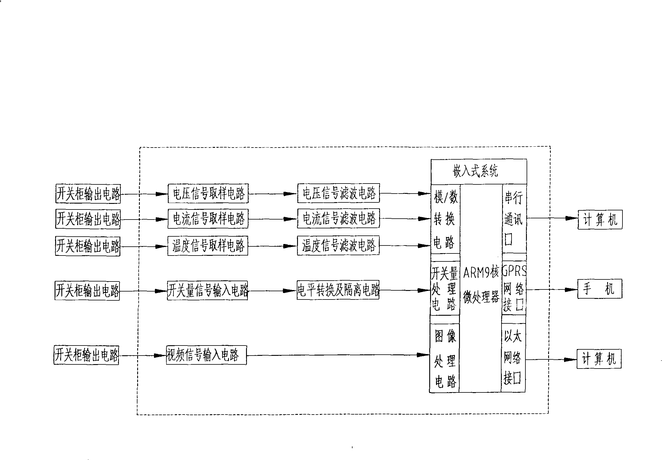
[0008] With reference to accompanying drawing 1, a kind of switchgear monitoring and management device of the present invention comprises the voltage signal sampling circuit that is connected with the switchgear output circuit, the output terminal of the voltage signal sampling circuit is connected with the voltage signal filter circuit, and the output terminal of the voltage signal filter circuit is connected with Analog / digital signal converter; and a current signal sampling circuit connected to the output circuit of the switch cabinet, the output terminal of the current signal sampling circuit is connected to the current signal filter circuit, and the output terminal of the current signal filter circuit is connected to the analog / digital signal converter; its characteristics Yes, the device is also equipped with a temperature signal sampling circuit connected to the output circuit of the switch cabinet, the output terminal of the temperature signal sampling circuit is connect...


PUM


Abstract

Disclosed is a switchboard monitoring and management device that is used to provide remote distance monitoring of the operation situation of an electric switch. The device comprises a voltage signal sampling circuit and a current signal sampling circuit that are in connection with an output circuit of the switchboard, and is characterized in that a temperature signal sampling circuit, a switching signal input circuit, a video signal input circuit and an ARM9 processor which is connected with the circuits that are in connection with the output circuit of the switchboard are arranged in the device, the output end of the ARM9 processor connects the device with a central supervisory control computer through a serial communication port of an embedded system or an Ethernet network interface, or connects the device with a cell phone through a GPRS network interface. The invention realizes the timely monitoring of the switchboard through transmission of signals including voltage, current, temperature, switching, video and the like; can automatically give an alarm when fault occurs; meanwhile, manufacturers can help users solve problems remotely so as to effectively reduce after-sale service costs of the manufacturers.

Description

technical field [0001] The invention relates to the technical field of circuit devices for power supply or distribution, in particular to a circuit device for providing remote monitoring and control of the operation of electric switches. Background technique [0002] The switchgear is a necessary equipment for power system distribution of electric energy; the switchgear currently used is mainly composed of primary equipment and secondary equipment; among them, the primary equipment includes circuit breakers, load switches, disconnectors, grounding switches, current transformers, and voltage transformers. The secondary equipment consists of ammeter, voltmeter, relay protection device, charged display, condensation controller, button, transfer switch, indicator light, air switch, watt-hour meter Due to the large number of additional equipment and complex connections, it brings trouble to the operation and is very easy to cause misoperation; during the operation of the equipmen...

Claims


Application Information

Patent Timeline
Patent Type & Authority Applications(China)
IPC IPC(8): H02J13/00
Inventor 程晓弘
Owner NINGBO TIANAN GRP CO LTD
Learn More