
Signal detection method for stochastic access channel

A technology of random access channel and signal detection, applied in the field of communication, can solve the problems of increasing signaling overhead and system processing burden, and achieve the effect of reducing signaling overhead, ensuring successful access, and avoiding missed detection

Active Publication Date: 2009-01-28
ZTE CORP
View PDF0 Cites 37 Cited by
  • Summary
  • Abstract
  • Description
  • Claims
  • Application Information

AI Technical Summary

Problems solved by technology

A large number of false alarms will increase the signaling overhead in the random access process and increase the processing burden of the system, so false alarms need to be suppressed

Method used


Image

  • Signal detection method for stochastic access channel
  • Signal detection method for stochastic access channel
  • Signal detection method for stochastic access channel

Examples


Embodiment Construction

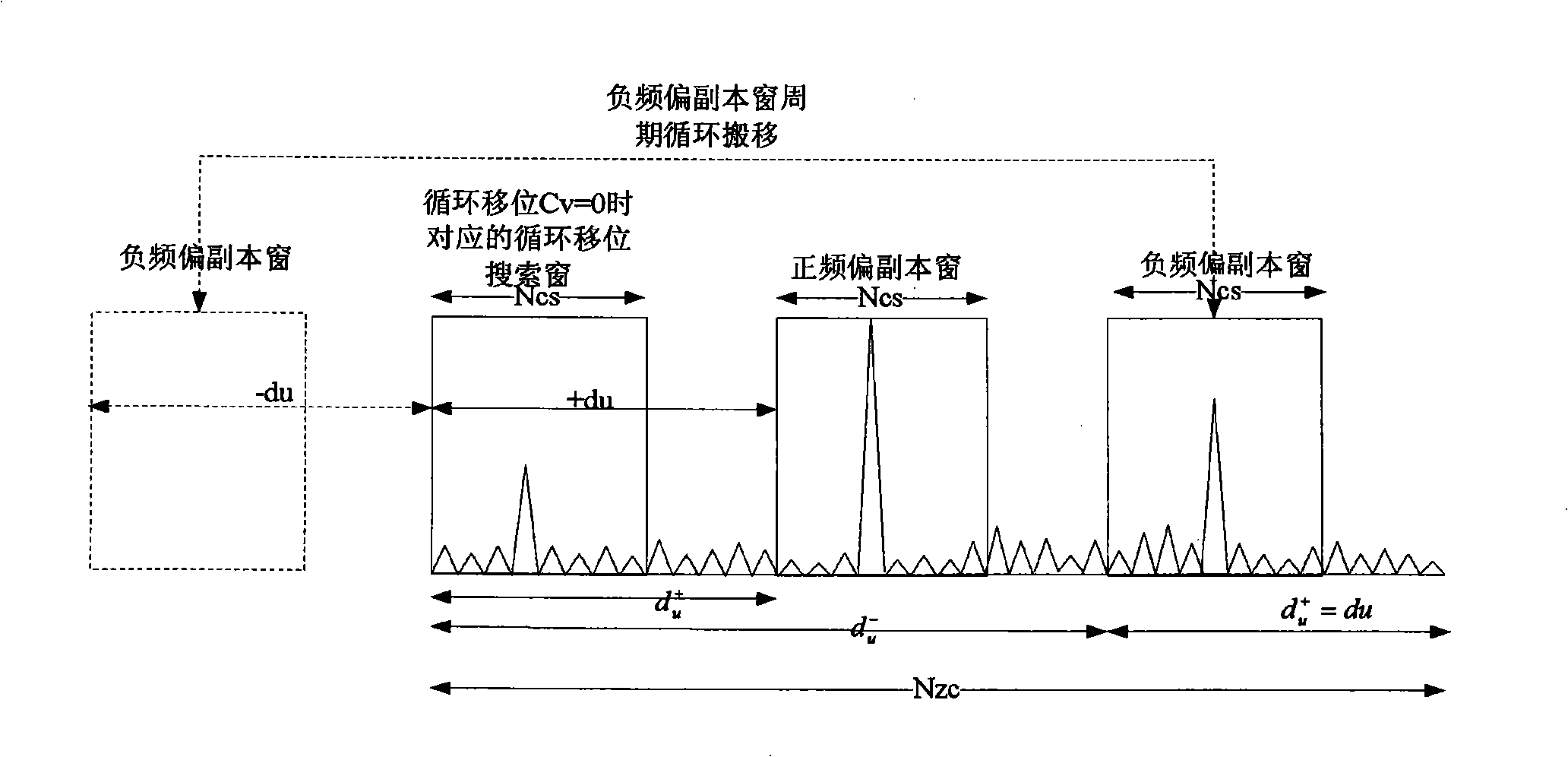
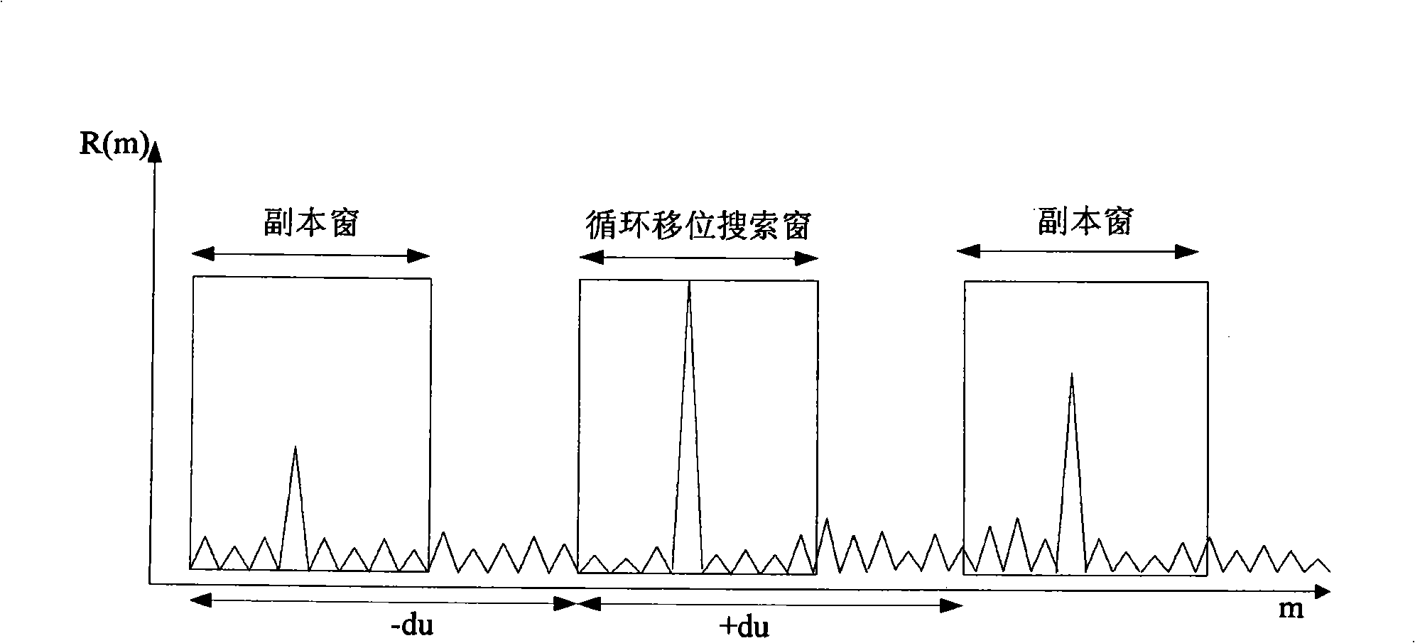
[0070] The basic thought of the present invention is, because frequency offset can cause a large number of false alarms, therefore can find the position of these false alarms according to the frequency offset characteristic of ZC sequence when carrying out the peak detection in RACH time-domain correlation detection process, removes these possibility. It is the position of the false alarm to achieve the purpose of false alarm suppression.

[0071] The present invention will be described in detail below with reference to the drawings and embodiments.

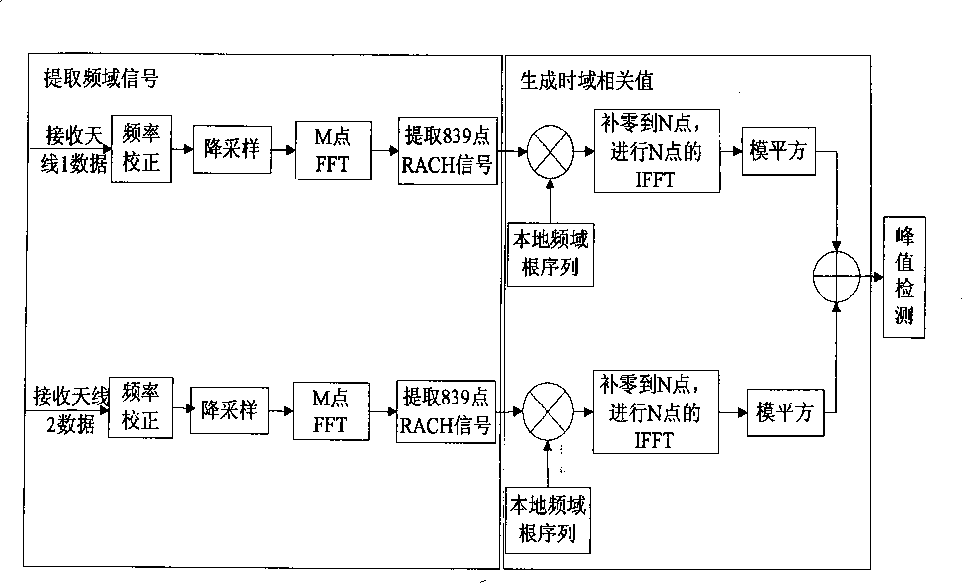
[0072] Figure 4 It is a flow chart of the RACH time-domain correlation detection method according to the embodiment of the present invention. In order to highlight the focus of the present invention, Figure 4 right figure 1 Parts are combined and simplified, and only a single receiving antenna is used as an example for description. Such as Figure 4 As shown, the method includes the following steps:

[0073] 401: Extract ...


PUM


Abstract

The invention provides a method for detecting the signals randomly accessed to a signal channel. The method comprises the steps: A. after a base station acquires N time domain correlation values R(m) of the u root sequence, and all m values corresponding to the N time domain correlation values are used as detection points; B. among all detection points, the detection point m_max corresponding to the biggest time domain correlation value is found out, when the biggest time domain correlation value R(m_max) is bigger than the peak detection threshold, whether lead codes randomly accessed to the signal channel is detected by a circular shift search window corresponding to the m_max is judged, the m_max and the point m1 and / or point m2 of the present detection points are used as non-detection points, wherein m1=(N+m_max-du)mod N, and m2=(m_max+du)mod N; C. if detection points are still left, the biggest time domain correlation value of the remained detection points is bigger than the peak detection threshold, the step B is jumped to, N is more than and equal to Nzc.

Description

technical field [0001] The invention relates to the communication field, in particular to a signal detection method of a random access channel. Background technique [0002] In the LTE (Long Term Evolution, long-term evolution) system, after the UE (User Equipment, user terminal) is turned on, it first performs downlink synchronization through the SCH (Synchronization Channel, synchronization channel), and finds the receiving start point and cell number of the radio frame and subframe ( CellID); then obtain system information through BCH (Broadcast Channel), the system information includes configuration information of RACH (RandomAccess Channel, random access channel); finally perform uplink synchronization through RACH to complete the work of accessing the system. [0003] In the process of uplink synchronization, the UE first finds the transmission position of the RACH channel based on the receiving starting point of the radio frame and subframe determined during the downl...

Claims


Application Information

Patent Timeline
IPC IPC(8): H04B7/26H04Q7/38
CPCH04J13/0062H04J11/00
Inventor 薛妍谭欢喜翟羽佳
Owner ZTE CORP
Learn More