
Exhaust gas purifying apparatus and exhaust gas purifying method using the same

An exhaust purification device and exhaust pipe technology, which is applied to the electronic control of exhaust treatment devices, exhaust devices, chemical instruments and methods, etc., can solve the problems of exhaust odor, catalyst function deterioration and change, etc. Effects of preventing sulfur poisoning, suppressing H2S production, and preventing functional degradation

Inactive Publication Date: 2009-01-21
TOYOTA JIDOSHA KK
View PDF5 Cites 8 Cited by
  • Summary
  • Abstract
  • Description
  • Claims
  • Application Information

AI Technical Summary

Problems solved by technology

[0008] However, in the exhaust purification devices described in Documents 1 to 5, since the exhaust gas flowing into the catalyst on the downstream side cannot quickly become lean, it cannot respond to sudden changes in the operating state of the internal combustion engine, and high-concentration H may be temporarily discharged. 2 S
In addition, the catalysts on the upstream side used in the exhaust gas purification devices described in Documents 1 to 5 purify the exhaust gas when the internal combustion engine is started, so they are basically small in size and are easily exposed to high temperatures. In the case of changing to a lean state, noble metal grains grow in a high-temperature lean atmosphere, and the catalytic function deteriorates
Therefore, in the exhaust purification devices described in Documents 1 to 5, the catalyst on the upstream side may not function sufficiently at the time of startup, and the exhaust gas may not be sufficiently purified.
In addition, even if NO is used in the catalyst on the downstream side x In the case of a storage catalyst or a so-called three-way catalyst, the sulfur component accumulated in the catalyst on the downstream side temporarily becomes high-concentration H 2 S detachment, exhaust odor often occurs

Method used


Image

  • Exhaust gas purifying apparatus and exhaust gas purifying method using the same
  • Exhaust gas purifying apparatus and exhaust gas purifying method using the same
  • Exhaust gas purifying apparatus and exhaust gas purifying method using the same

Examples


manufacture example 1

[0063] (Manufacturing example 1: Pt / CZ+Ni catalyst)

[0064] Using a carrier containing a ceria-zirconia solid solution (CZ carrier), a catalyst (Pt / CZ+Ni catalyst) in which platinum and nickel were supported on a CZ carrier was produced. That is, first, as a CZ carrier, the following carriers were used as stabilizers containing La in an amount of 3% by mass and 7% by mass, respectively. 2 o 3 and Pr 2 o 3 A solid solution (ceria content: 60% by mass, zirconia content: 40% by mass) mainly composed of ceria and zirconia, with a specific surface area of ​​about 100m 2 / g. The CZ support and alumina sol were mixed to prepare a catalyst slurry, and the above-mentioned catalyst slurry was coated on a honeycomb substrate containing cordierite to support it, and then fired at a temperature of 500°C to obtain a support coating. Substrate. Then, the carrier-coated substrate is adsorbed and loaded with platinum, fired at a temperature of 500° C., and the nickel nitrate aqueous sol...

manufacture example 2

[0065] (Manufacturing example 2: Pt / CZ+Fe catalyst)

[0066]A catalyst (Pt / CZ+Fe catalyst) in which platinum and iron were supported on a CZ carrier was obtained in the same manner as in Production Example 1, except that an aqueous nitrate solution of iron (Fe) was used instead of an aqueous solution of nickel nitrate. . In addition, the loadings of platinum, CZ carrier, alumina sol and iron in the obtained catalyst were respectively: 0.03g of platinum per liter of catalyst, 150g of CZ carrier per liter of catalyst, and 20g of oxide oxide per liter of catalyst. Aluminum sol, 0.05mol iron per liter of catalyst.

Embodiment 1

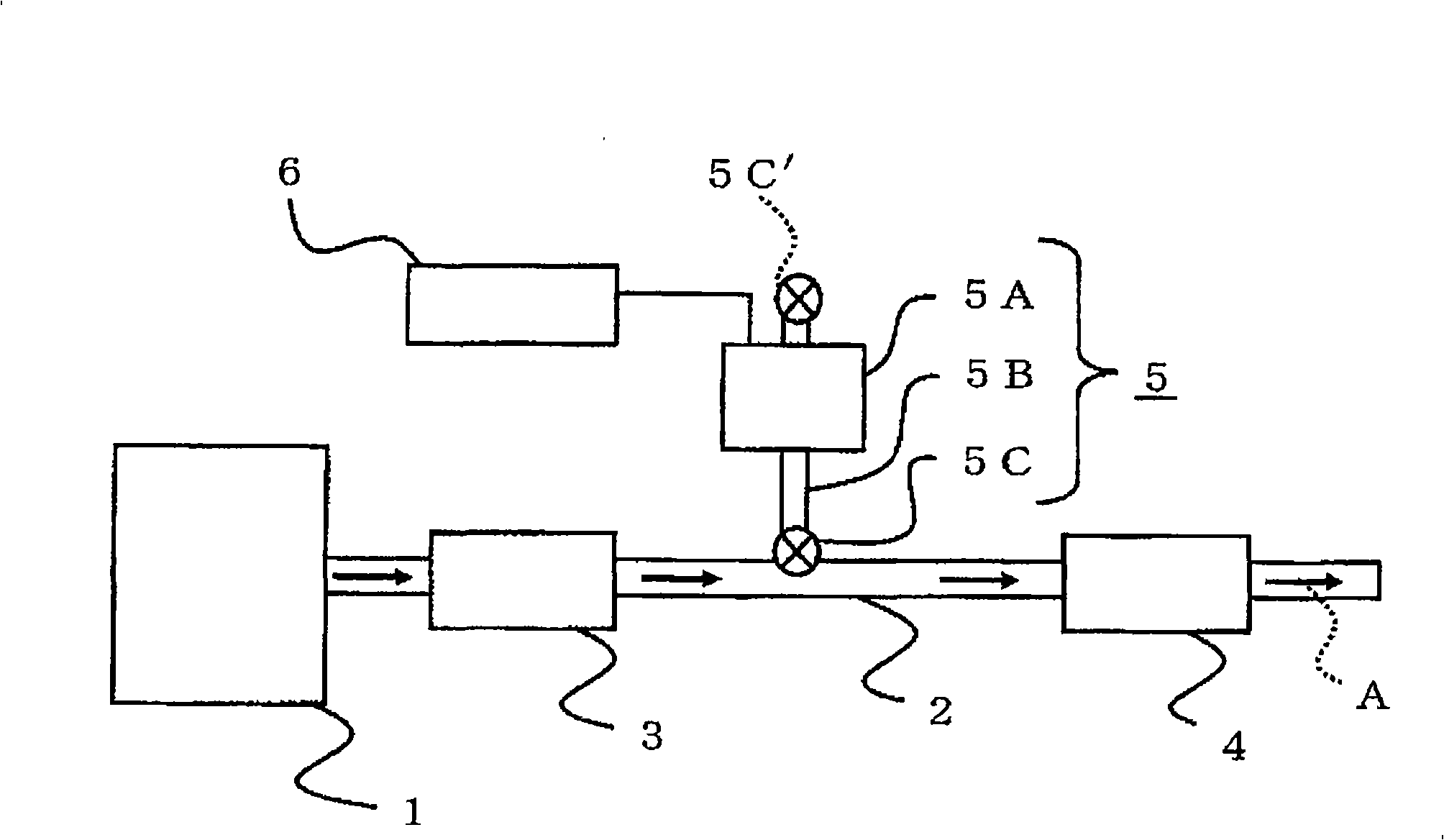
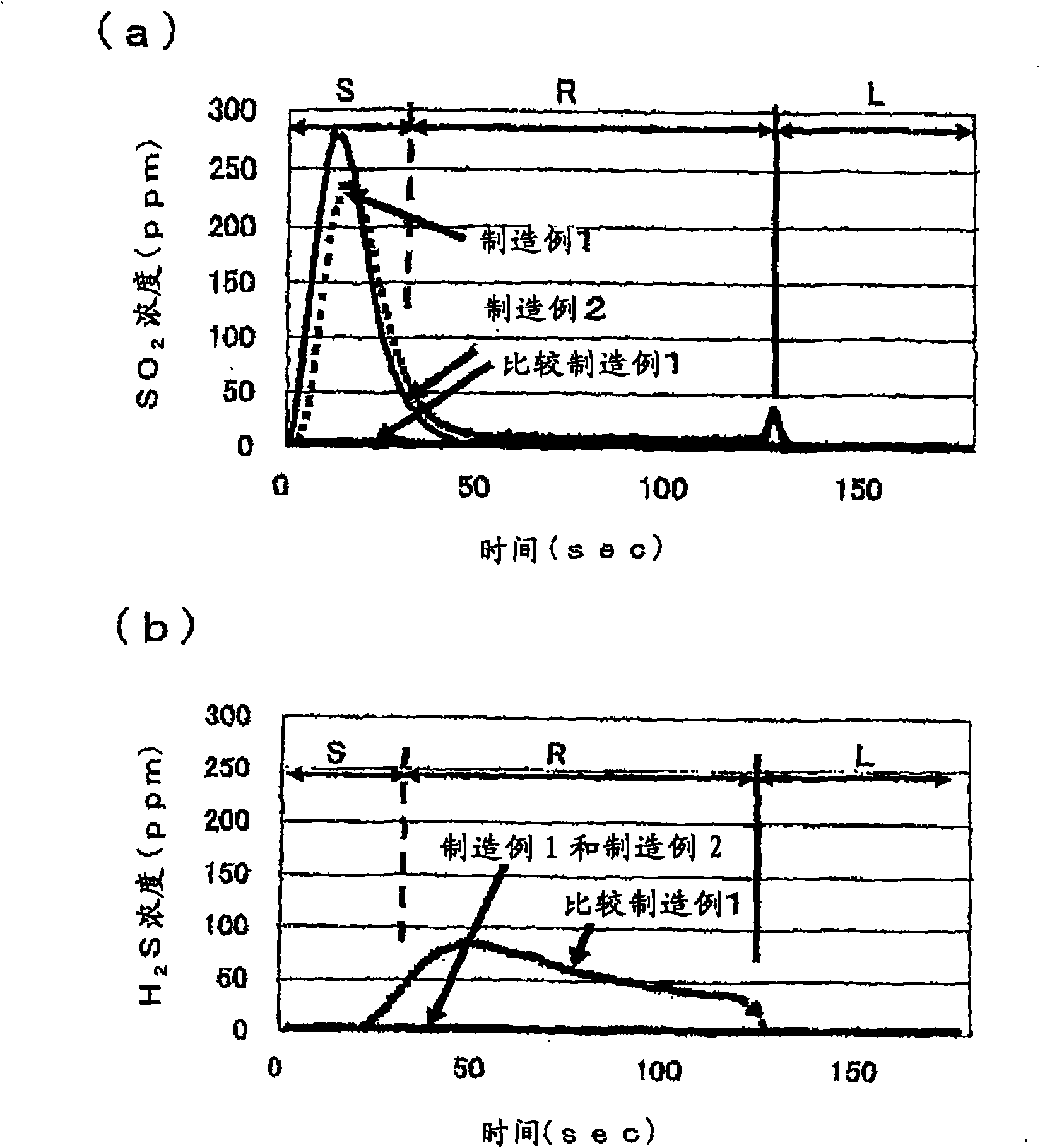
[0079] Install the exhaust purification device in the exhaust system of a car equipped with a 2.4L gasoline engine to conduct a model test and measure the H contained in the exhaust gas 2 S and SO 2 concentration. That is, it is first used as an exhaust purification device figure 1 The exhaust gas purifying device of the structure shown, wherein, as the upstream catalyst 3 has a commercially available three-way catalyst (Pt-Rh / (alumina+CZ) catalyst), as the downstream catalyst 4 has the Pt / The CZ+Fe catalyst has a small pump with a gas supply capacity of 30 L / min as the oxidizing gas supply pump 5A, a bimetal intake valve as the intake valve 5C, and an ECU as the control unit 6 . Then, the following model test was carried out, that is: the automobile in which the above-mentioned exhaust purification device was installed in the exhaust system of a 2.4L gasoline engine was driven on the chassis under the test conditions of the American model (LA#4), and then Accelerate rapi...


PUM

PropertyMeasurementUnit
specific surface areaaaaaaaaaaa

Abstract

Disclosed is an exhaust gas purifying apparatus comprising an exhaust gas pipe (2) connected to an internal combustion engine (1), an upstream catalyst (3) arranged on the upstream side of the exhaust gas passage in the exhaust gas pipe (2), a downstream catalyst (4) arranged on the downstream side of the exhaust gas passage in the exhaust gas pipe (2) and loaded with nickel and / or iron, and an oxidizing gas supply means (5) connected between the upstream catalyst (3) and the downstream catalyst (4) in the exhaust gas pipe (2) for supplying an oxidizing gas into the exhaust gas pipe (2).

Description

technical field [0001] The present invention relates to an exhaust purification device and an exhaust purification method using the same. Background technique [0002] As a catalyst for purifying gases exhausted from gasoline engines, so-called NO x Storage catalysts, three-way catalysts, etc. are being put into practical use. Among them, NO x The storage catalyst generally has a function of storing NO in the exhaust gas from the internal combustion engine when the air-fuel ratio of the exhaust gas is in a lean state. x , when the air-fuel ratio of the exhaust gas from the internal combustion engine is in the state of stoichiometric air-fuel ratio (stoichiometric ratio) or in a rich state, the NO stored by it is released x to restore. In addition, such catalysts have: In addition to storing NO x In addition, the sulfur (S) component contained in the exhaust gas is regarded as a property of sulfate storage. Such a sulfur component, due to its stability compared to NO x...

Claims


Application Information

Patent Timeline
Patent Type & Authority Applications(China)
IPC IPC(8): F01N3/20F01N3/22F01N3/24B01D53/94B01J23/89
CPCB01J37/0242F01N2560/025F01N2013/023F01N3/0814B01D2251/102F01N2610/146F01N2900/08B01D2251/11F01N13/02B01J23/002Y02T10/47F01N3/32F01N3/021Y02T10/22F01N9/00F01N2610/08F01N3/0842B01D53/9445F01N3/0885B01D53/9459F01N2560/06B01J23/894B01D2255/20753F01N2610/04B01D53/9477F01N3/206B01D2255/20738B01J2523/00F01N13/009F01N13/0093Y02T10/12Y02T10/40Y02A50/20B01J2523/3706B01J2523/3712B01J2523/3718B01J2523/48B01D53/94B01J23/89F01N3/20F01N3/22
Inventor 铃木正高桥直树蜂须贺一郎
Owner TOYOTA JIDOSHA KK
Learn More