Sensor system and sensor

A sensor and temperature sensor technology, applied in the field of sensor systems, can solve the problems of easy damage, excessive size, and high price

Inactive Publication Date: 2009-01-21
TETRA LAVAL HLDG & FINANCE SA
View PDF0 Cites 1 Cited by
  • Summary
  • Abstract
  • Description
  • Claims
  • Application Information

AI Technical Summary

Problems solved by technology

Some of the existing concentration sensors used so far have proven to be accurate, but in general they (as in the case of IR-sensors) are very fragile, bulky and too expensive for the desired application

Method used


Image

  • Sensor system and sensor
  • Sensor system and sensor
  • Sensor system and sensor

Examples


Embodiment Construction

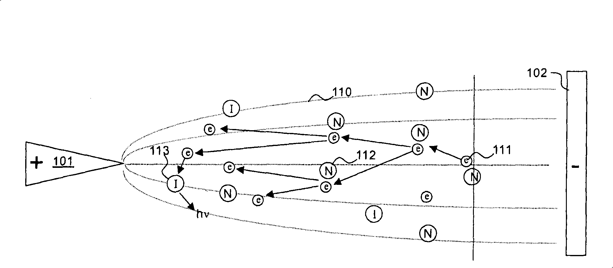
[0030] Before focusing on the sensor system of the present invention, the following reference image 3 , briefly discussing some principle aspects of corona current measurement.

[0031] image 3 is an explanatory sketch showing the principle of corona discharge. A first electrode 101 is arranged at a distance from a second electrode 102 connected to ground potential, the two electrodes together forming a corona gap. In this embodiment, a positive potential of several kV is applied to the electrode, creating an electric field, represented by electric field lines 110 . As a result, free electrons 111 begin to move in the applied electric field, forming an electric current or corona current. As electrons approach the electrode 101, they are accelerated to the point where collisions with neutral molecules 112 will create more free electrons, and so on. This avalanche effect amplifies the corona current.

[0032] The driving force in the above process is the relative differen...


PUM


Abstract

A sensor system for measurement of a concentration of a sterilizing agent in a sterilizing device utilized in production of packages comprises a sensor (300), adapted for arrangement in a volume of sterilization gas for measurement of concentration of the same, an electronic processing circuit, for evaluation of an output from the sensor, and an I / O-unit for communication with process-control systems. The inventive sensor system further comprises a high voltage power supply for operation of the sensor, a first electrode (301), which together with a second electrode (302) arranged at a distance from the first forms a corona gap. The system utilizes measurement of electrical properties of this gap, when a voltage is applied over the gap and a corona current is flowing between the electrodes (301, 302), to determine the concentration of sterilizing agent in the gap. The present invention also relates to a sensor.

Description

technical field [0001] The invention relates to a sensor system for measuring the concentration of disinfectant in a sterilization plant for the production of packages. The invention also relates to a device for sterilizing packages comprising the sensor system. The invention also relates to a sensor for measuring the concentration of a gaseous disinfectant. Background technique [0002] A kind of equipment for container 8 disinfection such as figure 1 shown (from SE0203692-9). The device 1 typically consists of a housing divided into several regions. In the first zone, heating zone 2, hot air is introduced for heating the packages. In the second zone, the disinfection zone 3 , hydrogen peroxide is introduced for disinfection of the heated containers 8 . Hydrogen peroxide is injected through nozzle 13 . In the third zone, discharge zone 4 , hot sterilized gas is introduced for discharge of containers 8 and in the final zone, filling zone 5 , packages 8 are filled with ...

Claims


Application Information

Patent Timeline
Patent Type & Authority Applications(China)
IPC IPC(8): G01N27/68
CPCA61L2/208A61L2/24A61L2202/23A61L2/22A61L2202/18G01N27/70
Inventor 托尔比约恩·罗森勒夫佩尔·奥兰德斯安德斯·彼得松安东尼·格劳泽爱德华·科尔比
Owner TETRA LAVAL HLDG & FINANCE SA
Why Eureka
Try Eureka