
Camera exposure optimization techniques that take camera and scene motion into account

A relative motion and scene technology, applied in the field of automatic exposure control, can solve the problem of not considering camera motion or scene motion

Active Publication Date: 2009-01-14
QUALCOMM INC
View PDF1 Cites 18 Cited by
  • Summary
  • Abstract
  • Description
  • Claims
  • Application Information

AI Technical Summary

Problems solved by technology

The automatic exposure processing of existing cameras does not take into account the motion of the camera or the motion of the scene when calculating the exposure parameters used to capture an image of the scene

Method used


Image

  • Camera exposure optimization techniques that take camera and scene motion into account
  • Camera exposure optimization techniques that take camera and scene motion into account
  • Camera exposure optimization techniques that take camera and scene motion into account

Examples


Embodiment Construction

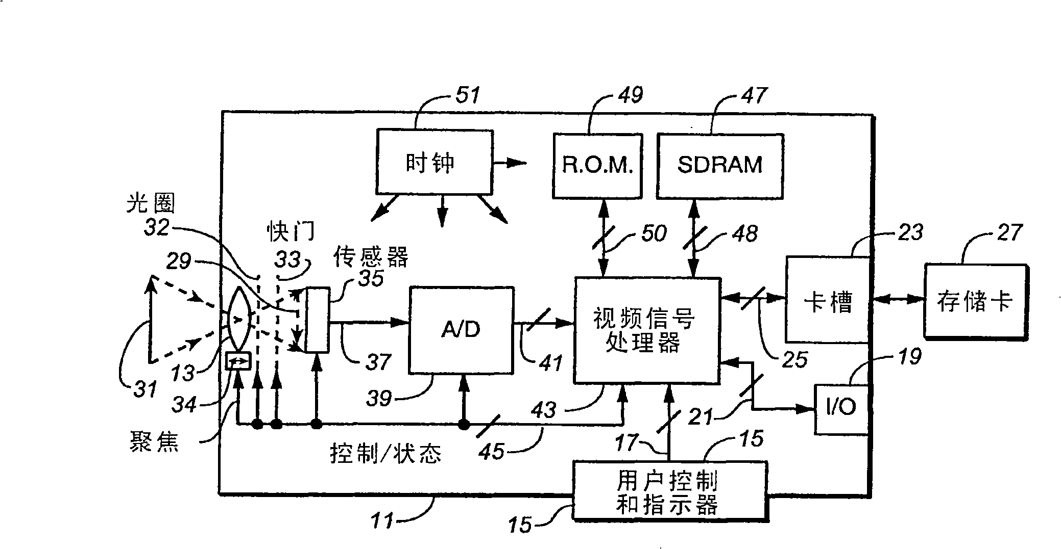
[0019] Video data obtained by digital cameras is often processed to compensate for camera imperfections and generally to improve the quality of images obtainable from the data. Correction of any defective pixel photodetector elements of the sensor is one processing function that can be performed. Another is white balance correction, where the relative magnitudes of different pixels of the primary color are set to render white. Such processing also includes demosaicing the individual pixel data to overlay data from the sensor's spatially separated monochrome pixel detectors to provide overlaid multicolor pixels in the image data. This demosaicing then entails manipulation of the data to enhance and smooth the edges of the image. In addition, image data compensation is performed for noise and variation on the image of the camera optical system and for variation between sensor photodetectors. Other processing typically includes one or more of gamma correction, contrast stretchi...


PUM


Abstract

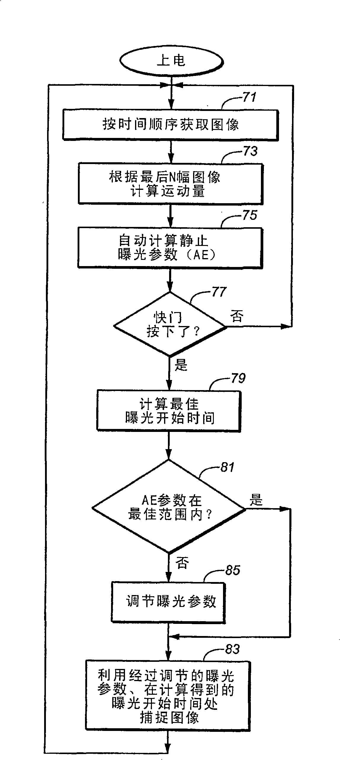
Quantities of motion between images of an electronic camera are calculated and used to adjust the exposure time and one or more other exposure parameters used to capture an image in order to improve the quality of the image. Motion blur caused by movement of the camera or by movement of an object within the scene being photographed is reduced by selecting appropriate exposure parameters. Further, when there is little or no motion detected, the exposure parameters may be selected to improve the depth of field and reduce the noise in the captured image.

Description

Background technique [0001] This invention relates to automatic exposure control for digital cameras and other electronic video capture devices, and more particularly to data in which optimal exposure parameters are calculated and utilized for capturing a still image or a continuous series of images. All patents, patent applications, articles, other publications, and matters cited herein are hereby incorporated by reference in their entirety for all purposes. [0002] The electronic camera images the scene onto a two-dimensional sensor such as a charge-coupled device (CCD), complementary metal-on-silicon (CMOS) device, or other type of light sensor. These devices consist of a large number of photodetectors (typically 2, 3, 4 million or more) arranged on a small two-dimensional surface, each of which generates light or other optical radiation ( Includes a signal proportional to the intensity of the infrared and ultraviolet regions of the spectrum adjacent to the wavelengths of...

Claims


Application Information

Patent Timeline
IPC IPC(8): H04N5/235H04N5/232
CPCH04N5/23248H04N5/2327G03B2217/005H04N23/684H04N23/68
Inventor 西蒙·皮尔塞尔埃利·波尼安斯凯欧哈德·梅伊塔夫
Owner QUALCOMM INC
Learn More