
Controller for direct injection engine

一种控制器、发动机的技术,应用在发动机控制、燃烧发动机、机器/发动机等方向,能够解决不能充分地减少排放、燃料燃料量不能有效地被减少等问题

Inactive Publication Date: 2009-01-14
DENSO CORP
View PDF2 Cites 21 Cited by
  • Summary
  • Abstract
  • Description
  • Claims
  • Application Information

AI Technical Summary

Problems solved by technology

Therefore, even if split injection is performed, the injected fuel cannot be well atomized and the amount of wet fuel cannot be effectively reduced, thus failing to sufficiently reduce the emission

Method used


Image

  • Controller for direct injection engine
  • Controller for direct injection engine
  • Controller for direct injection engine

Examples


Embodiment Construction

[0017] Embodiments of the present invention are described below.

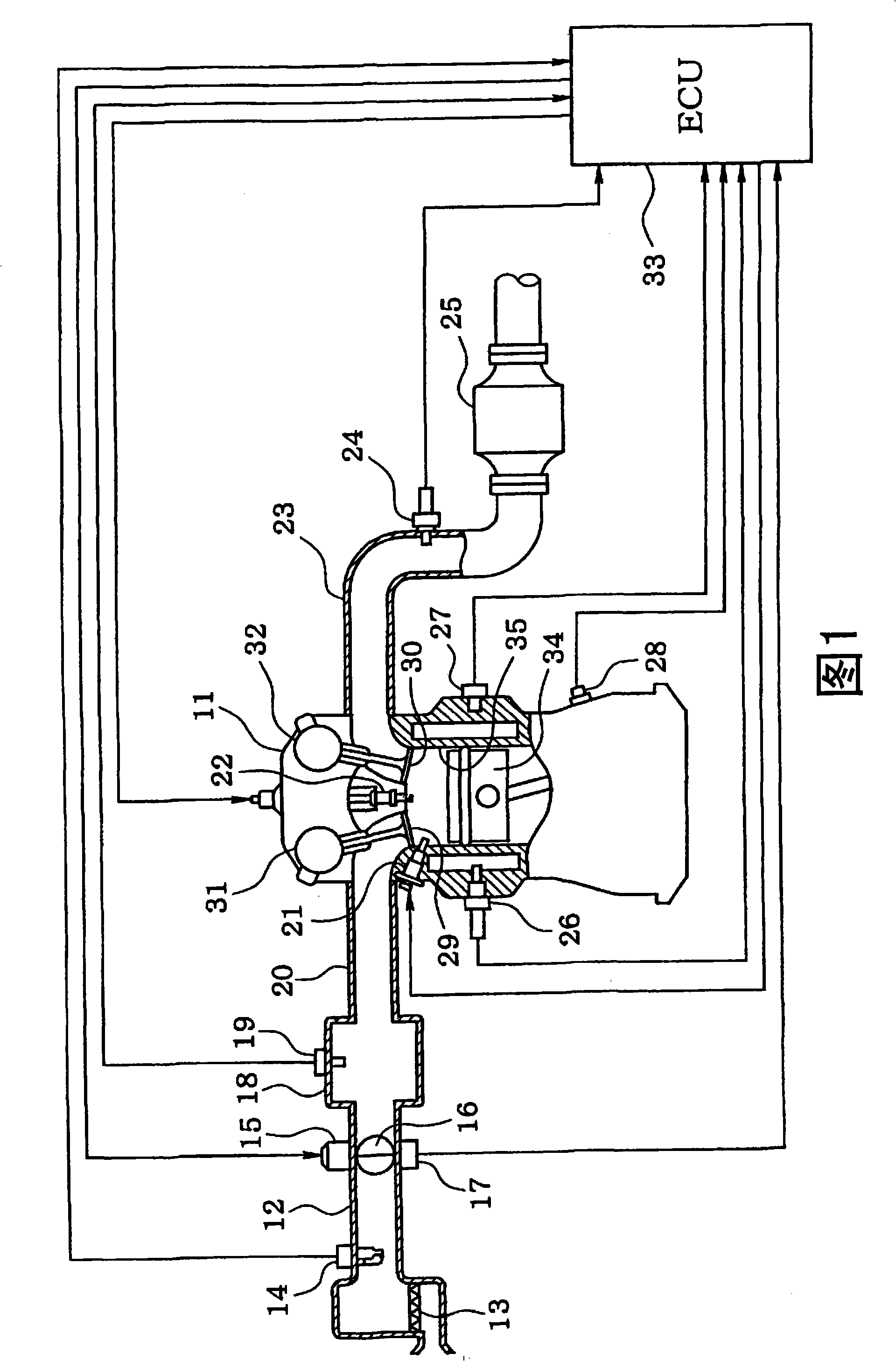
[0018] Referring to Fig. 1, an engine control system is explained. The air cleaner 13 is arranged upstream of the intake pipe 12 of the internal combustion engine 11 , which is a direct injection engine. An air flow meter 14 that detects the flow rate of intake air is provided on the downstream side of the air cleaner 13 . A throttle valve 16 driven by a DC motor 15 and a throttle position sensor 17 that detects a throttle position (throttle opening) are provided on the downstream side of the air flow meter 14 .

[0019] A surge tank 18 including an intake pressure sensor 19 is disposed downstream of the throttle valve 16 . The intake air pressure sensor 19 detects intake air pressure. Intake manifold 20 is connected to surge tank 18 . A fuel injector 21 is installed on each cylinder on the vicinity of the intake port so as to directly inject fuel into the cylinder. A spark plug 22 is installed on a cylind...


PUM


Abstract

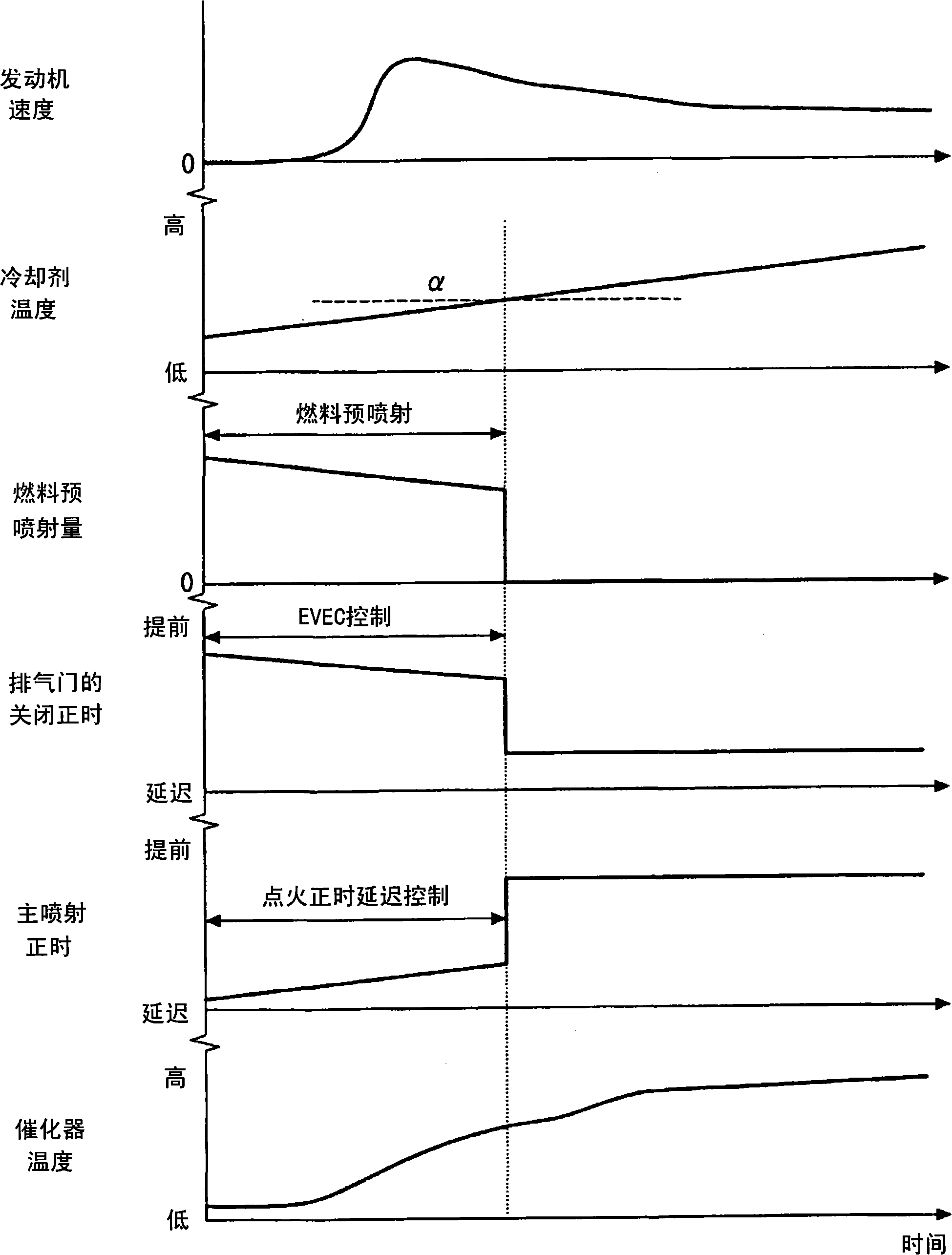
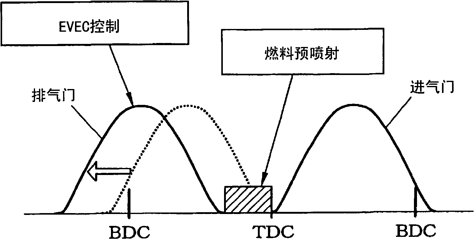
The present invention relates to a controller of a direct injecting type engine. When an engine is at starting or at cold state, a closing time of an exhaust valve is set before an intake top dead center to close the exhaust valve early. An exhaust residual gas is compressed by a cylinder to raise an inner cylinder temperature. A pre-fuel injection is performed from a time of closing the exhaust valve to a time of the intake top dead center in such a manner that the pre-injected fuel is combusted to raise the inner cylinder temperature. This increase in temperature expedites an atomization of fuel injected at a main fuel injection. A wet amount of fuel is reduced and HC emission is also reduced.

Description

technical field [0001] The present invention relates to a controller for a direct injection engine that injects fuel directly into cylinders. Background technique [0002] A direct injection engine was developed to improve fuel economy, reduce emissions and increase output. In such a direct injection engine, when the engine is started or cold (before warming up), the fuel injected into the cylinder is difficult to atomize and tends to stick to the inner surface of the cylinder or the upper surface of the piston. If these adhered fuels increase, the amount of fuel used for combustion decreases, so that the driving condition of the engine becomes unstable. The adhering fuel quantity is referred to below as the wet fuel quantity. [0003] When the engine is started or in a cold state, if the fuel injection amount is increased, more fuel is used for combustion, resulting in stable combustion. However, if the amount of fuel is increased, the amount of wet fuel is also increase...

Claims


Application Information

Patent Timeline
Patent Type & Authority Applications(China)
IPC IPC(8): F02D43/00
CPCF02D41/06F02B2075/125Y02T10/44Y02T10/18F02D13/0219F02D2013/0292F02D2041/001Y02T10/123F02D41/064F02D13/0249F02D41/403F02B23/104Y02T10/12Y02T10/40F02D13/0265
Inventor 井上正臣
Owner DENSO CORP
Learn More