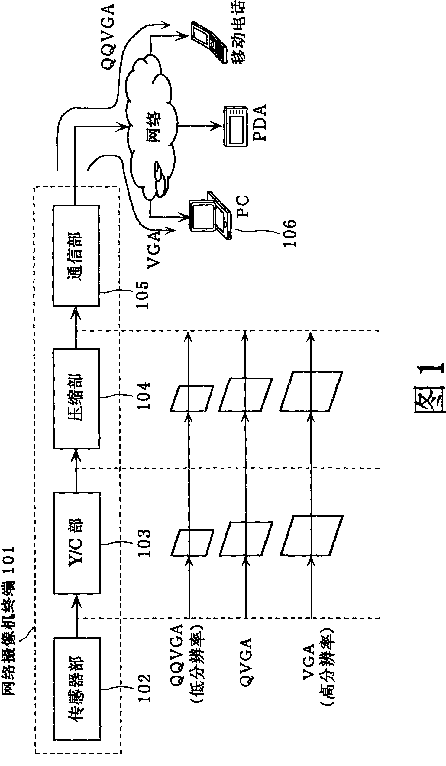
Data communication device and data communication method
A data communication and data stream technology, applied in image communication, digital video signal modification, pulse modulated television signal transmission, etc. Effect
- Summary
- Abstract
- Description
- Claims
- Application Information
AI Technical Summary
Problems solved by technology
Method used
Image
Examples
Embodiment 1
[0077] Embodiment 1 of the data communication device according to the present invention will be described below with reference to the drawings.
[0078] In addition, the network camera terminal according to the first embodiment is characterized in that I frames corresponding to each data stream are generated at an I frame generation rate described in a generation table held in advance by the frame control unit. Also, the network camera terminal in the description of the following embodiments corresponds to the data communication device described in the claims.
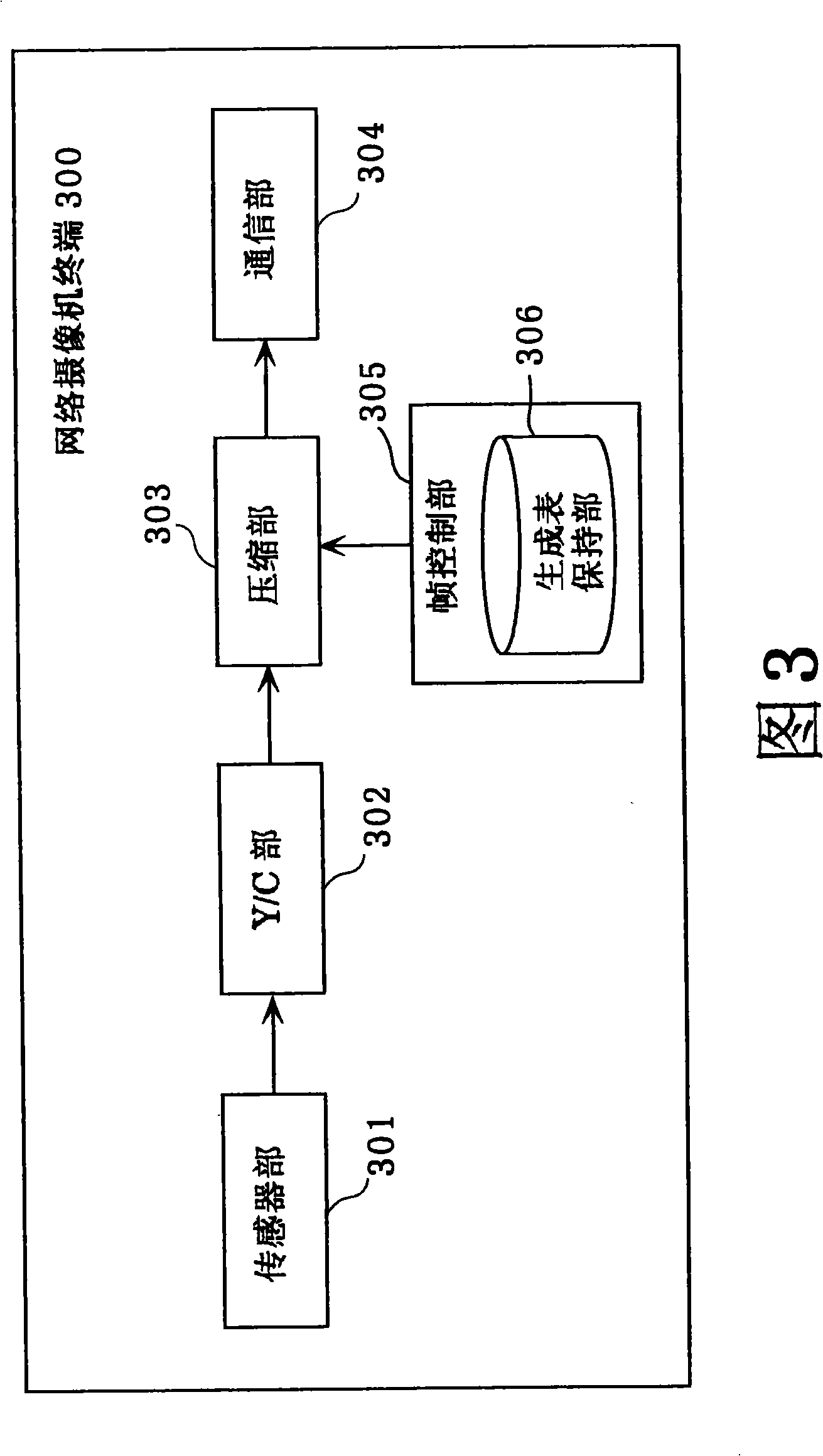
[0079] FIG. 3 is a functional block diagram showing the configuration of a network camera terminal 300 according to the first embodiment.
[0080] The network camera terminal 300 according to the first embodiment includes a sensor unit 301 that inputs image information, a Y / C unit 302 that performs Y / C processing on images taken from the sensor unit 301, and compresses and encodes Y / C data to generate encoded frames. ...
Embodiment 2
[0091] A second embodiment of the present invention will be described below with reference to the drawings.
[0092] Furthermore, the network camera terminal according to the second embodiment is characterized in that the network camera terminal does not use a generation table to fix the generation rate of I frames in each stream as in the above-mentioned embodiment 1, and the generation rate of I frames in each stream When the rate is changed, the down counter unit included in the frame control unit is used to control so that I frames are not repeatedly generated in a plurality of streams.
[0093] FIG. 8 is a functional block diagram showing the configuration of a network camera terminal 800 according to the second embodiment.
[0094] The network camera terminal 800 according to the second embodiment includes, in addition to the configuration of the above-mentioned first embodiment, a down counter unit 305a for counting the number of control frames generated in each of the ...
Embodiment 3
[0104] A third embodiment of the present invention will be described below with reference to the drawings.
[0105] 10 is a functional block diagram showing the structure of a network camera terminal 1000 according to the third embodiment, which is characterized in that, in addition to the structure of the first embodiment, it also includes a frequency band monitoring unit 1001 for monitoring the communication frequency band of the communication unit 304 .
[0106] Hereinafter, the operation processing of the network camera terminal 1000 in the third embodiment will be described.
[0107] First, image information is input from the sensor unit 301 . The sensor unit 301 digitally converts the image information and sends it to the Y / C unit 302 . The Y / C unit 302 reads the digital data transmitted from the sensor unit 301 , converts the data size after Y / C processing, and sends it to the compression unit 303 as Y / C data.
[0108] Next, the compression unit 303 receives the Y / C d...
PUM
 Abstract
Description
Claims
Application Information
 - R&D
- Intellectual Property
- Life Sciences
- Materials
- Tech Scout
- Unparalleled Data Quality
- Higher Quality Content
- 60% Fewer Hallucinations
Browse by: Latest US Patents, China's latest patents, Technical Efficacy Thesaurus, Application Domain, Technology Topic, Popular Technical Reports.
© 2025 PatSnap. All rights reserved.Legal|Privacy policy|Modern Slavery Act Transparency Statement|Sitemap|About US| Contact US: help@patsnap.com


