
Ethylene pyrolysis furnace

A technology of ethylene cracking furnace and radiant furnace tube, which is used in cracking, hydrocarbon cracking to hydrocarbon production, non-catalytic thermal cracking, etc. Covering area, improving radiation heat transfer efficiency, preventing the effect of secondary reaction

Active Publication Date: 2008-12-31
WISON ENG
View PDF1 Cites 42 Cited by
  • Summary
  • Abstract
  • Description
  • Claims
  • Application Information

AI Technical Summary

Problems solved by technology

[0003] Patent CN1730449A describes a kind of ethylene cracking furnace structure and single-row arrangement of radiation furnace tubes. Although the cracking furnace of this kind of furnace tube arrangement has improved the traditional radiation furnace tube arrangement, it still has the following disadvantages: (1) in Under the premise of equivalent production capacity, the length of the furnace is longer than that of other cracking furnaces, and the volume of the cracking furnace is larger and the floor area is larger. Therefore, its manufacturing cost is higher; (2) The cracking furnace with alternately arranged inlet and outlet furnace tubes The distance between the furnace and the inlet and outlet furnace tubes is not large, which makes it very difficult to set up the hanging system of the radiation furnace; (3) The increase in the length of the cracking furnace not only has an adverse effect on the temperature distribution of the flue gas in the radiation chamber of the cracking furnace, At the same time, it is difficult to further improve the production capacity of a single cracking furnace
Its advantages are: compared with traditional pyrolysis, when it reaches the same production capacity, it has a smaller volume and a smaller footprint; its disadvantages are: (1) The inlet and outlet pipes of the radiation furnace tubes are arranged in a centralized manner, and the radiation furnace The heating of the tube will become uneven, and the use efficiency of the radiant furnace tube will be reduced; (2) The bottom of the inlet and outlet furnace tubes is connected with a straight pipe section through a 90° elbow, and the flexibility of the radiant furnace tube is limited, which is not conducive to absorbing the inlet and outlet furnace tubes. The thermal expansion of the tube is poor, which can easily lead to the bending of the radiant furnace tube, which will reduce the operational safety of the cracking furnace if the bending is serious

Method used


Image

  • Ethylene pyrolysis furnace
  • Ethylene pyrolysis furnace
  • Ethylene pyrolysis furnace

Examples


no. 1 Embodiment

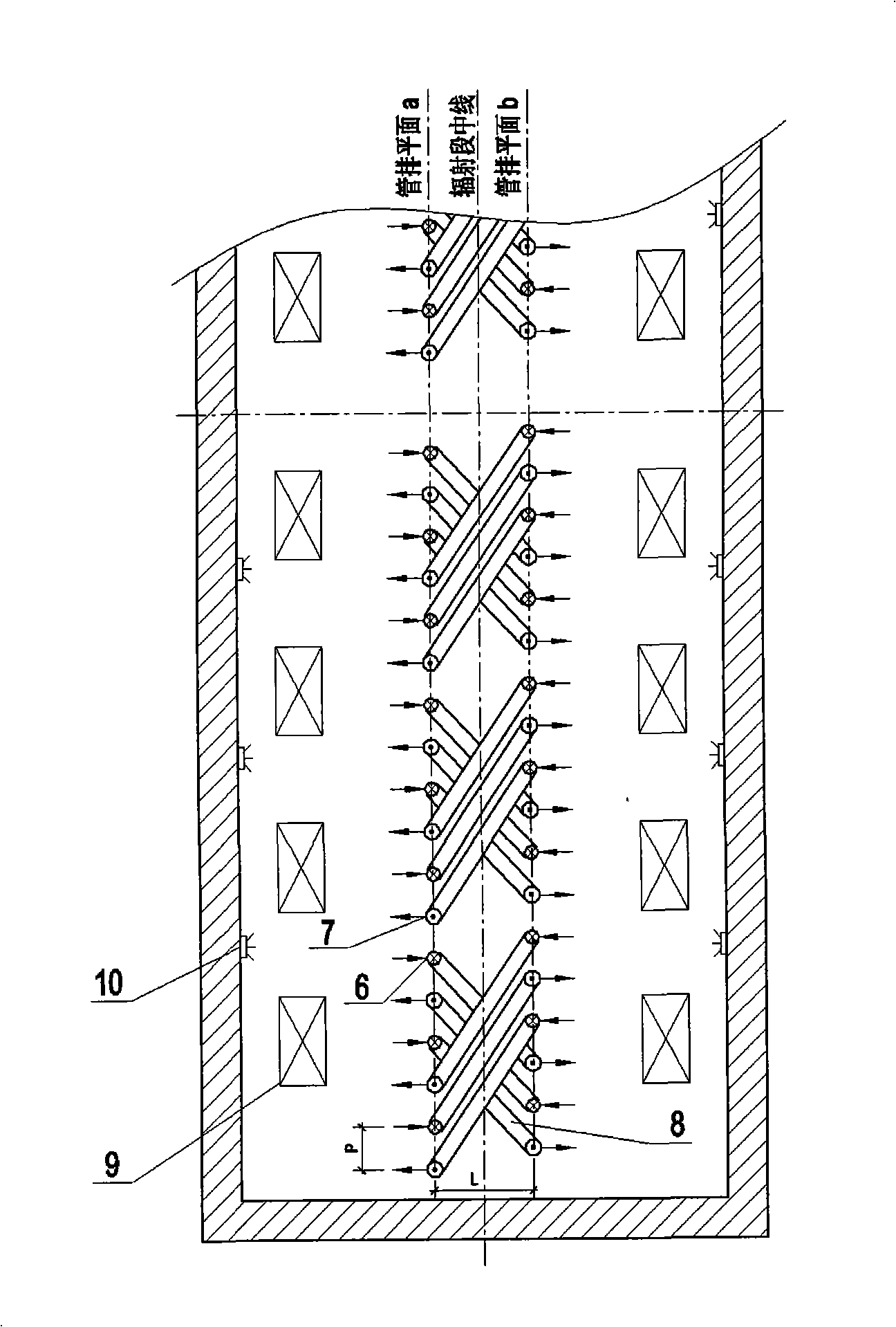
[0023] first embodiment :like image 3 As shown, 64 radiation furnace tubes are arranged in each radiation room, and every 16 radiation furnace tubes is a large group, and each radiation room has a total of four groups of such radiation furnace tubes. If there is only one such radiation chamber in the radiation section, the ethylene production capacity of the cracking furnace can reach 60,000-80,000 tons / year; if there are two such radiation chambers in the radiation section, the ethylene production capacity of the cracking furnace can reach 12-160,000 tons / year. Several important dimensions of the cracking furnace are: the distance L between the two radiant furnace tube row planes is 500mm, the distance P between the inlet and outlet pipes is 214mm, the inner diameter of the inlet pipe is 50mm, the inner diameter of the outlet pipe is 61mm, and the length of the radiation chamber is about 15m .

no. 2 Embodiment

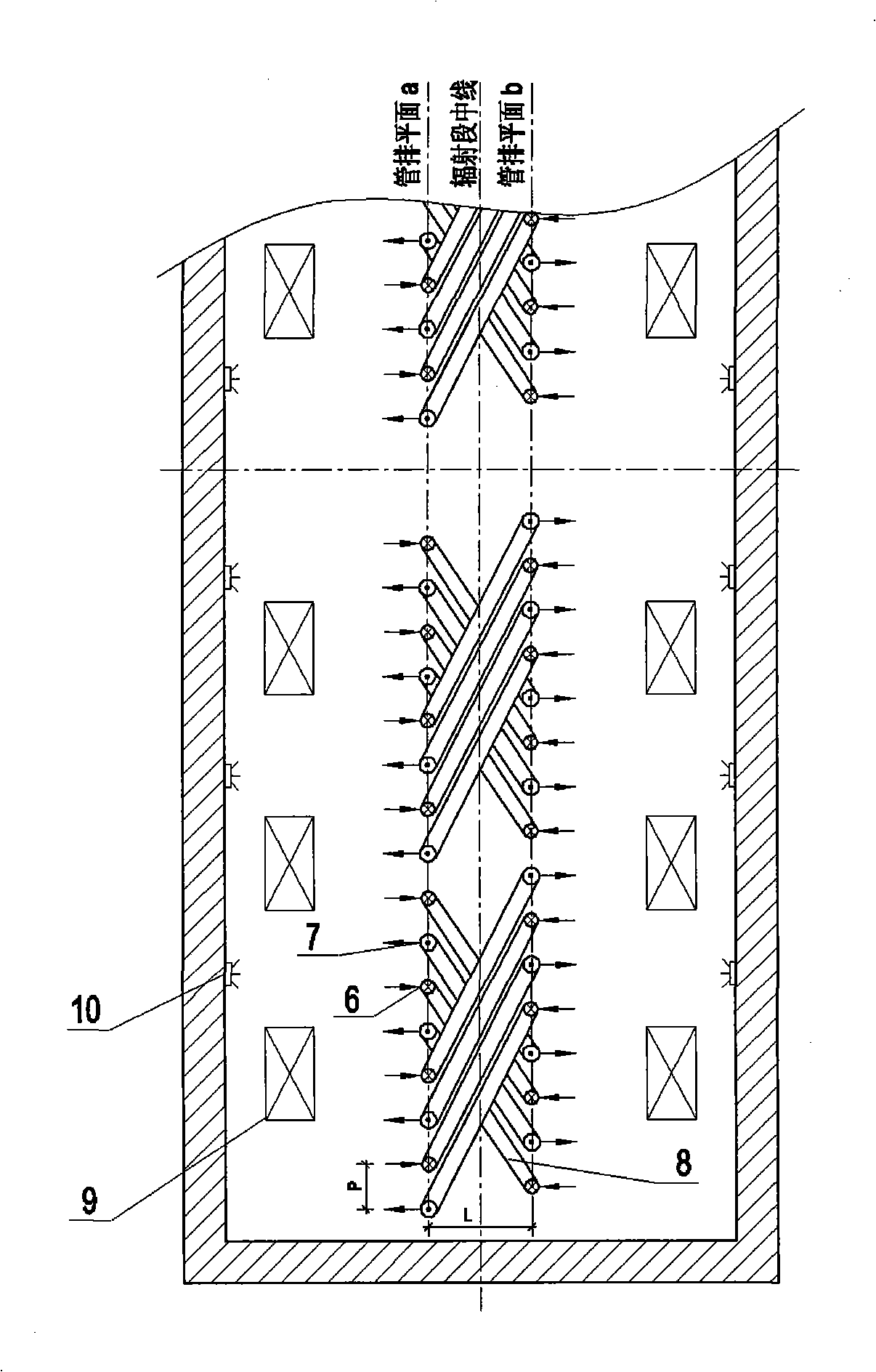
[0024] 2nd embodiment :like Figure 4 As shown, 72 radiation furnace tubes are arranged in each radiation room, and each 18 radiation furnace tubes is a large group, and there are four groups of such radiation furnace tubes in each radiation room. If there is only one such radiation chamber in the radiation section, the ethylene production capacity of the cracking furnace can reach 70,000 to 100,000 tons / year; if there are two such radiation chambers in the radiation section, the ethylene production capacity of the cracking furnace can reach 14-200,000 tons / year. Several important dimensions of the pyrolysis furnace are: the spacing L of the tube row is 500mm, the spacing P of the inlet and outlet tubes is 214mm, the inner diameter of the inlet tube is 50mm, the inner diameter of the outlet tube is 61mm, and the length of the radiation chamber is about 17.5m.

no. 3 Embodiment

[0025] 3rd embodiment :like Figure 5 As shown, 80 radiation furnace tubes are arranged in each radiation room, and every 20 radiation furnace tubes is a large group, and there are four groups of such radiation furnace tubes in each radiation room. If there is only one such radiation chamber in the radiation section, the ethylene production capacity of the cracking furnace can reach 90,000 to 110,000 tons / year; if there are two such radiation chambers in the radiation section, the ethylene production capacity of the cracking furnace can reach 180,000 to 220,000 tons / year. Several important dimensions of the pyrolysis furnace are: the spacing L of the tube row is 500mm, the spacing P of the inlet and outlet tubes is 214mm, the inner diameter of the inlet tube is 50mm, the inner diameter of the outlet tube is 61mm, and the length of the radiation chamber is about 19m.


PUM


Abstract

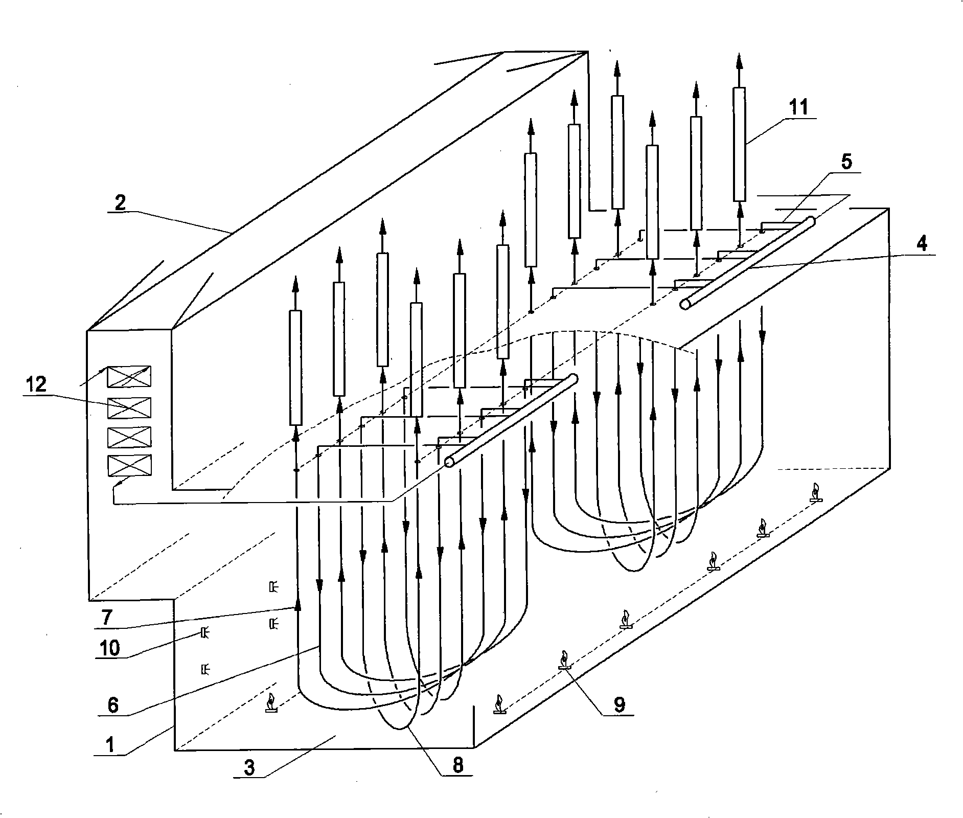
An ethylene cracking furnace comprises a radiation segment, a convection segment, a bottom burner, sidewall burners and a quench boiler; the radiation segment is provided with a radiation room; radiation furnace tubes used for the pyrolysis of hydrocarbons and petroleum distillate are arranged inside the radiation room; each radiation furnace tube is composed of an inlet tube and an outlet tube; each inlet tube and each outlet tube are respectively provided with one channel; at least a radiation room 3 is arranged in the radiation segment of the cracking furnace; the radiation furnace tubes are arranged in two rows in the radiation room; each row of radiation furnace tubes forms a tube row plane; an inlet tube 6 and an outlet tube 7 of a radiation furnace tube are in two different tube row planes in an alternating interval way; the bottom parts of the inlet tube 6 and the outlet tube 7 are connected together through a symmetrical U-connector 8. The invention achieves a large-scale cracking furnace; the furnace tube arrangement way of the invention improves the radiation heat transfer efficiency of the radiation furnace tubes so as to prolong the operating cycle of the cracking furnace and reduce energy consumption of products.

Description

Technical field: [0001] The invention relates to a cracking furnace for producing olefins such as ethylene and propylene by pyrolyzing hydrocarbons and petroleum fractions. The utility model belongs to the field of hydrocarbon oil cracking equipment. Background technique: [0002] Since the successful development of the vertically suspended standpipe cracking furnace in the 1960s, ethylene cracking technology has made great progress. At present, the ethylene cracking furnace licensors are focusing their research on increasing the size of the cracking furnace, improving the selectivity of the cracking furnace, increasing the product yield, improving the safety of the cracking furnace operation, reducing the energy consumption of the product, and reducing the construction cost of the cracking furnace. . [0003] Patent CN1730449A describes a kind of ethylene cracking furnace structure and single-row arrangement of radiation furnace tubes. Although the cracking furnace of thi...

Claims


Application Information

Patent Timeline
IPC IPC(8): C07C11/04C07C4/04
CPCC10G9/18C10G9/20C10G2400/20
Inventor 李保有薄建民涂国华刘海军李延生赵旭郭英锋
Owner WISON ENG
Learn More