Eureka AIR delivers breakthrough ideas for toughest innovation challenges, trusted by R&D personnel around the world.

Method for integrating inner-humidification fuel batter with proton exchange film

A proton exchange membrane and fuel cell technology, which is applied to fuel cell components, solid electrolyte fuel cells, fuel cells, etc., can solve the problems of inability to uniformly manufacture and use materials, waste materials, and reduce the power density of battery packs. working area, improving integration compactness, increasing the effect of power density

Inactive Publication Date: 2008-12-17
SHANGHAI SHENLI TECH CO LTD
View PDF1 Cites 8 Cited by
  • Summary
  • Abstract
  • Description
  • Claims
  • Application Information

AI Technical Summary

Problems solved by technology

As a result, the length of the entire humidification section or the length of the power generation section increases, thereby reducing the power density of the entire battery pack
[0024] ②The existence of these additional irregular diversion holes makes the processing of the diversion plate and humidification diaphragm of the battery pack humidification section or the diversion plate and electrodes of the power generation section must be specially designed and considered, because the diversion of the humidification section The plates and humidifying diaphragms are completely different from the deflectors and electrodes of the battery segment in shape, and many materials such as sealing rings cannot be uniformly produced and used, thus wasting a lot of materials

Method used


Image

  • Method for integrating inner-humidification fuel batter with proton exchange film
  • Method for integrating inner-humidification fuel batter with proton exchange film
  • Method for integrating inner-humidification fuel batter with proton exchange film

Examples


Embodiment 1

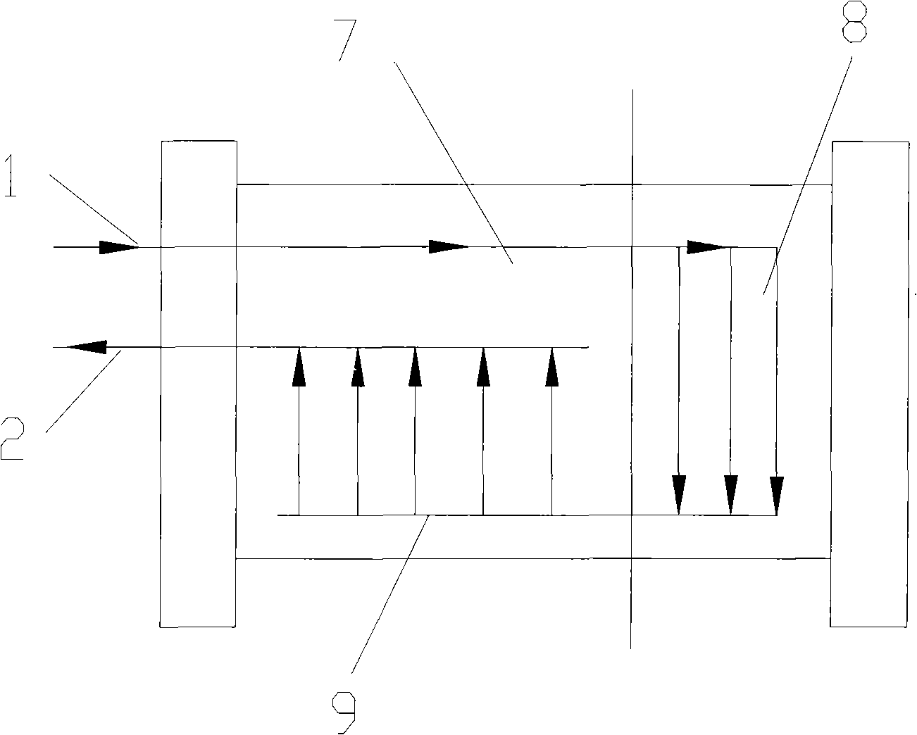
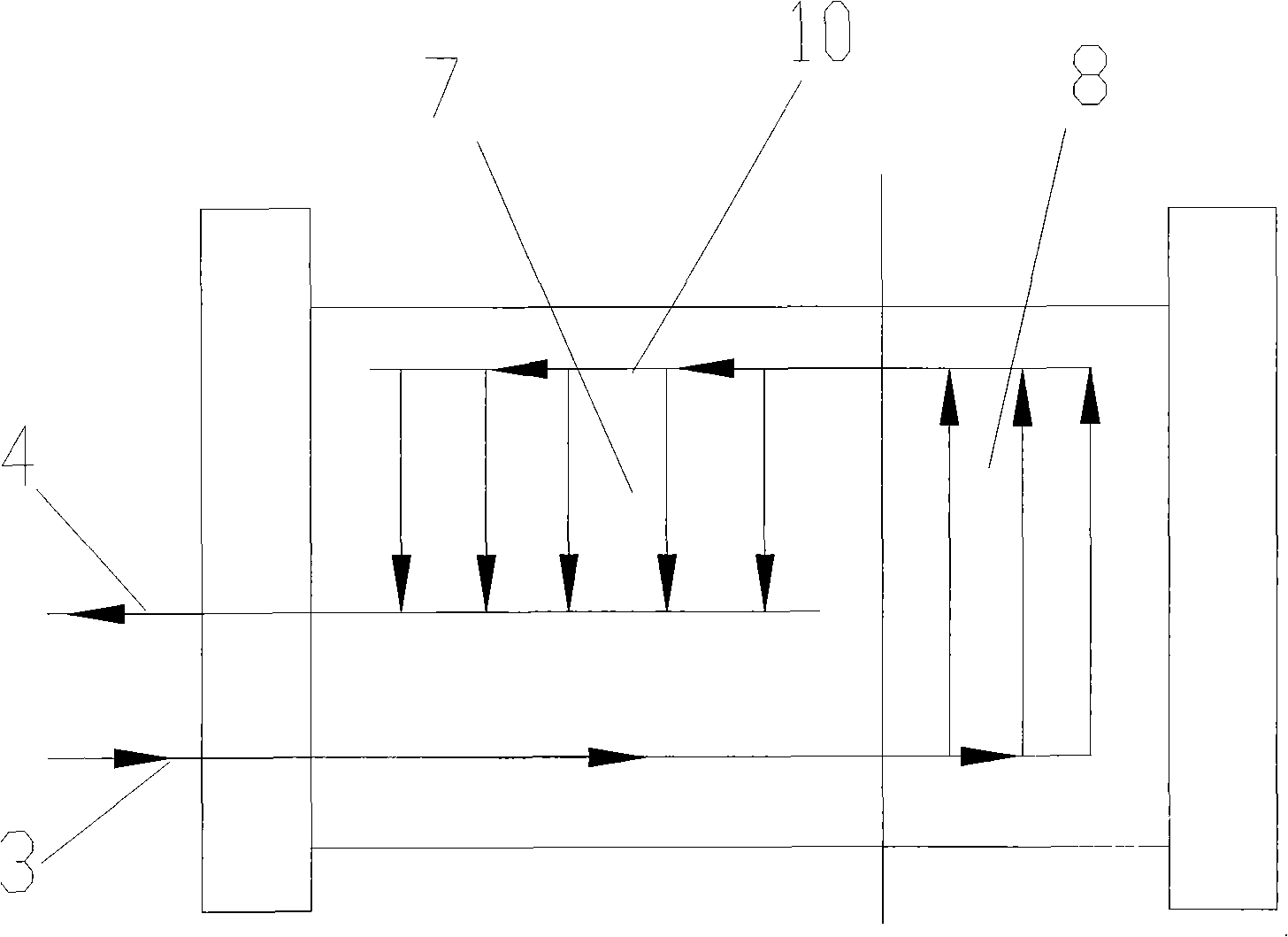
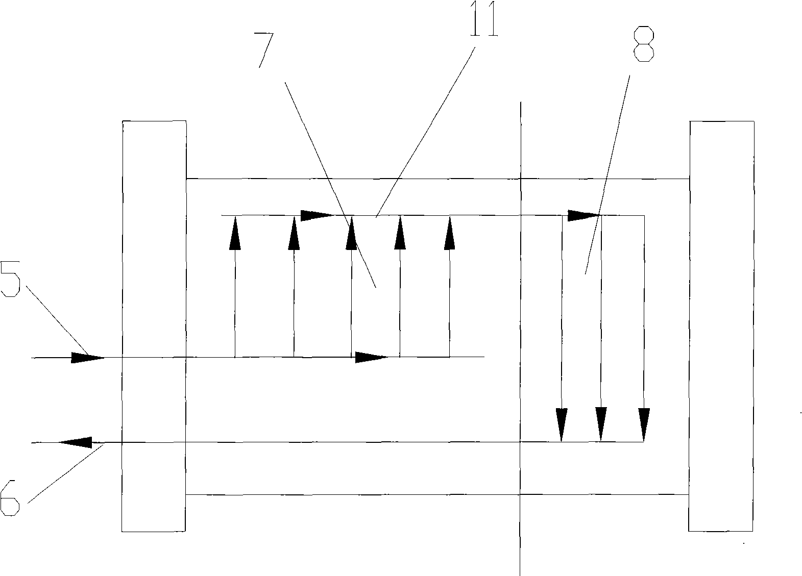
[0059] An integrated method for internally humidified proton exchange membrane fuel cells, such as Figure 5 As shown, the method is to integrate two groups of fuel cell stacks A and B into an integrated assembly, and a central collector plate 12 is arranged in the middle of the two groups of fuel cell stacks, and the fuel cell stacks A and B respectively include humidification sections A1 and B1 and the power generation section A2, B2, the humidification section A1, B1 is close to the central collector plate 12, the power generation section A2, B2 is close to the rear collector end plate 13 at the end, and the central collector plate 12 is provided with an air inlet 1, a hydrogen inlet 2, Cooling water outlet 6, air outlet 2, hydrogen outlet 4, cooling water inlet 5 are provided on the end rear collecting end plate 13; Figure 3a , 3b As shown, the air and hydrogen flow in from the air inlet 1 and the hydrogen inlet 2 of the central collector plate 12 in the middle and are d...

Embodiment 2

[0063] Such as Figure 7 As shown, it is an integrated fuel cell stack for forklift designed and assembled according to the new method of the present invention. Image 6 As shown, the central collector plate 12 is provided with an air inlet 1, a hydrogen inlet 3, and a cooling water outlet 6, and the collector end plates at the ends of stacks A and B are respectively provided with an air outlet 2, a hydrogen outlet 4, and a cooling water inlet 5. The two groups of fuel cell stacks A and B are respectively arranged at the left and right ends of the central collector plate 12, and hydrogen and air flow in from the air inlet 1 and the hydrogen inlet 2 on the central collector plate 12 and then divide into two branches, which flow into respectively In the humidification sections A1 and B1 of the fuel cell stacks A and B at the left and right ends, the humidified air and hydrogen enter the power generation sections A2 and B2 to undergo electrochemical reactions, and then flow from...

Embodiment 3

[0066] Such as Figure 8 As shown, it is another integrated fuel cell stack for a forklift designed and assembled according to the method of the present invention. Inlet 1, hydrogen inlet 3, cooling water outlet 6, air outlet 2, hydrogen outlet 4, and cooling water inlet 5 are respectively provided on the collector end plates at the ends of stacks A and B. The two groups of fuel cell stacks A and B are arranged up and down on the same side of the central collector plate 12, and hydrogen and air flow in from the air inlet 1 and hydrogen inlet 2 on the central collector plate 12 and then divide into two branches, which flow into the left and right respectively. Humidification sections A1, B1 of the end fuel cell stacks A, B, after the humidified air and hydrogen enter the power generation sections A2, B2 to undergo electrochemical reactions, then from the terminal rear collector end plate 13 behind the power generation sections A2, B2 The air outlet 2 and the hydrogen outlet 4 ...


PUM


Abstract

The invention relates to a method for integrating an internal humidifying proton exchange membrane fuel cell. The internal humidifying proton exchange membrane fuel cell comprises at least two groups of fuel cell stacks and a central current-collecting plate. The fuel cell stacks comprise a humidifying section and a power-generating section. The fuel cell stacks are arranged in the front / back / left / right positions or upper / bottom positions on two sides or on the same side of the central current-collecting plate. The humidifying section of the fuel cell stack is arranged close to the central current-collecting plate. An air inlet, a hydrogen inlet and a cooling water outlet are formed on the current-collecting plate. The air and the hydrogen enter the humidifying section from the central current-collecting plate, further enter the power-generating section after being humidified, then flow out of an end plate at the tail end of the power-generating section. The cooling water flows through a rear current-collecting end plate at the tail end of the power-generating section, cools the power-generating section by means of heat transfer, further flows into the humidifying section to humidify the air and the hydrogen therein, and finally flows out of the central current-collecting plate. Compared with the prior art, the internal humidifying proton exchange membrane fuel cell has the advantages of high effective working area, compact structure, etc.

Description

technical field [0001] The invention relates to a fuel cell, in particular to an integration method of a proton exchange membrane fuel cell with an internal humidifying device. Background technique [0002] An electrochemical fuel cell is a device that converts hydrogen fuel and oxidant into electrical energy and reaction products. The internal core component of the device is the membrane electrode (Membrane Electrode Assembly, referred to as MEA). The membrane electrode (MEA) is composed of a proton exchange membrane and two porous conductive materials, such as carbon paper, sandwiched between the two sides of the membrane. On the two boundary surfaces of the membrane and the carbon paper, there are even and finely dispersed catalysts for initiating electrochemical reactions, such as metal platinum catalysts. Conductive objects can be used on both sides of the membrane electrode to draw the electrons generated during the electrochemical reaction through an external circuit...

Claims


Application Information

Patent Timeline
Patent Type & Authority Applications(China)
IPC IPC(8): H01M8/24H01M8/10H01M8/04H01M8/02H01M8/0258H01M8/04119H01M8/2404
CPCY02E60/50
Inventor 胡里清李拯蒋亮珠
Owner SHANGHAI SHENLI TECH CO LTD
Why Eureka
Eureka Blog
Learn More