
Electric conduction-stirring friction composite heat power supply welding method and equipment

A friction stir welding and friction stir technology, which is applied in welding equipment, resistance welding equipment, non-electric welding equipment, etc., can solve the problems of limiting the improvement of welding quality and technological development, increasing the complexity of friction stir welding, and inaccurate temperature control. , to achieve the effects of easy popularization and application, reduction of welding defects, and uniform heating

Active Publication Date: 2010-09-01
罗键
View PDF7 Cites 3 Cited by
  • Summary
  • Abstract
  • Description
  • Claims
  • Application Information

AI Technical Summary

Problems solved by technology

However, the above method also has some defects: arc heating is not uniform, which easily causes stress concentration and deformation of the workpiece; at the same time, the use of electric arc to preheat the area to be welded, the temperature control is inaccurate, the metal may be melted or the preheating is insufficient, which increases the The complexity of friction stir welding, while the use of argon shielded arc increases the cost of welding, and the equipment is complicated, which limits the improvement of welding quality and technological development

Method used


Image

  • Electric conduction-stirring friction composite heat power supply welding method and equipment
  • Electric conduction-stirring friction composite heat power supply welding method and equipment

Examples


Embodiment Construction

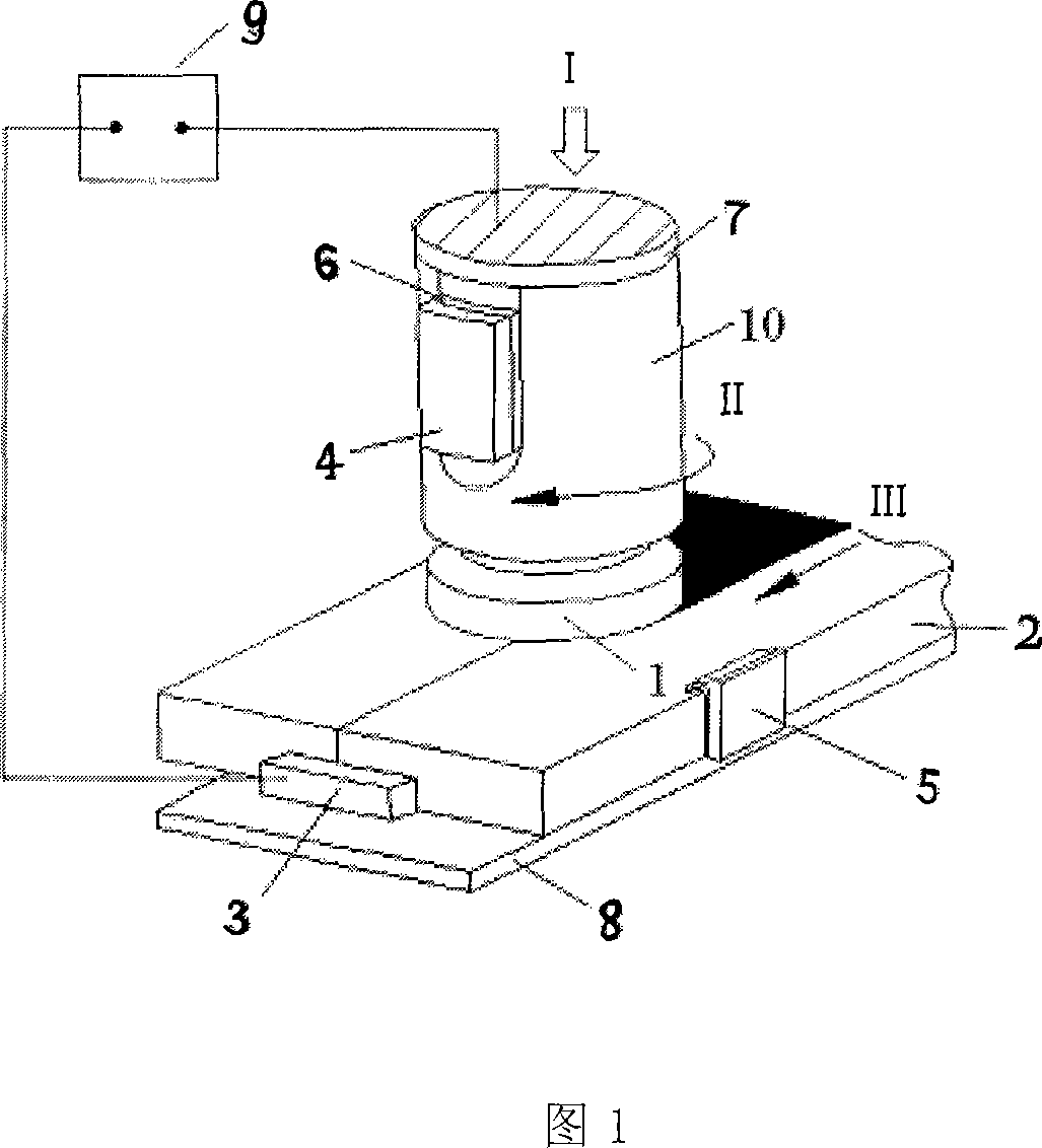
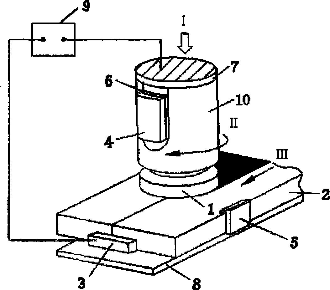
[0028]The present invention mainly provides a conductive-friction stir composite heat source welding method and equipment. The method and equipment generate resistance heat through conduction to assist friction stir welding, preheat before welding, and heat treat after welding to overcome the disadvantages of friction stir welding. When there is insufficient energy input (mainly refers to the welding of ferrous metals and high-temperature alloy structural materials), at the same time improve the quality of welded joints, prolong the service life of the stirring head, and reduce the occurrence of defects. This resistance heat and friction stir heat form a composite heat source for welding, thereby forming a more superior welding technique.

[0029] The present invention will be described in further detail below in conjunction with the accompanying drawings.

[0030] This conduction-friction stir compound heat source welding (abbreviation EFSW) method comprises general friction ...


PUM


Abstract

The invention discloses a conducting-stirring friction hybrid heat source welding method and a piece of equipment, wherein, in stirring friction welding, a stir head and a workpiece are simultaneously insulated from the main body of a welding machine, the clamp of a fixed workpiece and a worktable, current is galvanized in the weld seam direction of the workpiece, the current and the weld seam through which the current flows produce resistance heat with the contact resistance of a friction stirring welding area, and the resistance heat together with stirring friction heat forms the hybrid heat source of the stirring friction welding. The method and the equipment of the invention have the following remarkable effects: 1. the limitation of the stirring friction welding on welding materials is broken through, leading the stirring friction welding to be used for welding such structural materials as black ferrous metals, superalloy, and the like; 2. the service life of the stir head can beimproved; and 3. welding speed and welding quality can be further improved, thus improving the mechanical property of a welding joint. The method and the equipment of the invention can be used for the stirring friction welding, the preheating before welding, and the postweld heat treatment of such structural materials as carbon steel, stainless steel, and superalloy, etc.

Description

technical field [0001] The invention relates to the field of welding technology, in particular to a novel welding technology of a composite heat source formed by a friction stir heat source and a resistance heat source. Background technique [0002] In 1991, Wayne Thomas of the British Welding Institute (TWI) invented Friction Stir Welding (Friction StirWelding-FSW), which uses a special shape of the stirring head, by applying pressure to the stirring head, it is inserted into the joint surface of the material to be welded until The shoulder of the stirring head is in contact with the base metal surface. As the stirring head descends, the surface of the stirring head rubs against the base material to generate heat, and a spiral plastic fluid is formed around it, and a plastic fluid is generated under the shoulder at the same time, and the metal at the joint interface is in a thermoplastic state under the action of frictional heat , and start welding. Driven by the stirring...

Claims


Application Information

Patent Timeline
Patent Type & Authority Patents(China)
IPC IPC(8): B23K28/02B23K20/12B23K11/00B23K20/26B23K20/24
Inventor 罗键王颖
Owner 罗键
Learn More