Method for controlling clutch in vehicle transmission system equipped with friction type stepless speed changer

A friction clutch, clutch technology, applied in the direction of clutch, mechanical equipment, etc., can solve the problems of complex, inability to distinguish clutch slip, and the ability of the clutch to suppress torque vibration is weakened.

Active Publication Date: 2010-08-11
ROBERT BOSCH GMBH
View PDF9 Cites 0 Cited by
  • Summary
  • Abstract
  • Description
  • Claims
  • Application Information

AI Technical Summary

Problems solved by technology

[0006] The known method has the disadvantage that the control of the clutch slip is integrated with the control of the normal force of the transmission, so it is relatively complex
Also, this known control cannot distinguish whether an increase in clutch slip is due to said torque oscillations or a driver-initiated increase in engine torque
This means that the clutch's ability to dampen torque oscillations will be reduced during driver-initiated vehicle acceleration

Method used


Image

  • Method for controlling clutch in vehicle transmission system equipped with friction type stepless speed changer
  • Method for controlling clutch in vehicle transmission system equipped with friction type stepless speed changer
  • Method for controlling clutch in vehicle transmission system equipped with friction type stepless speed changer

Examples


Embodiment Construction

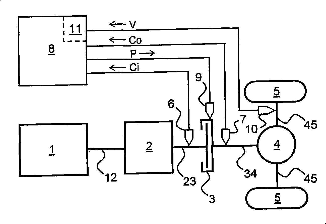
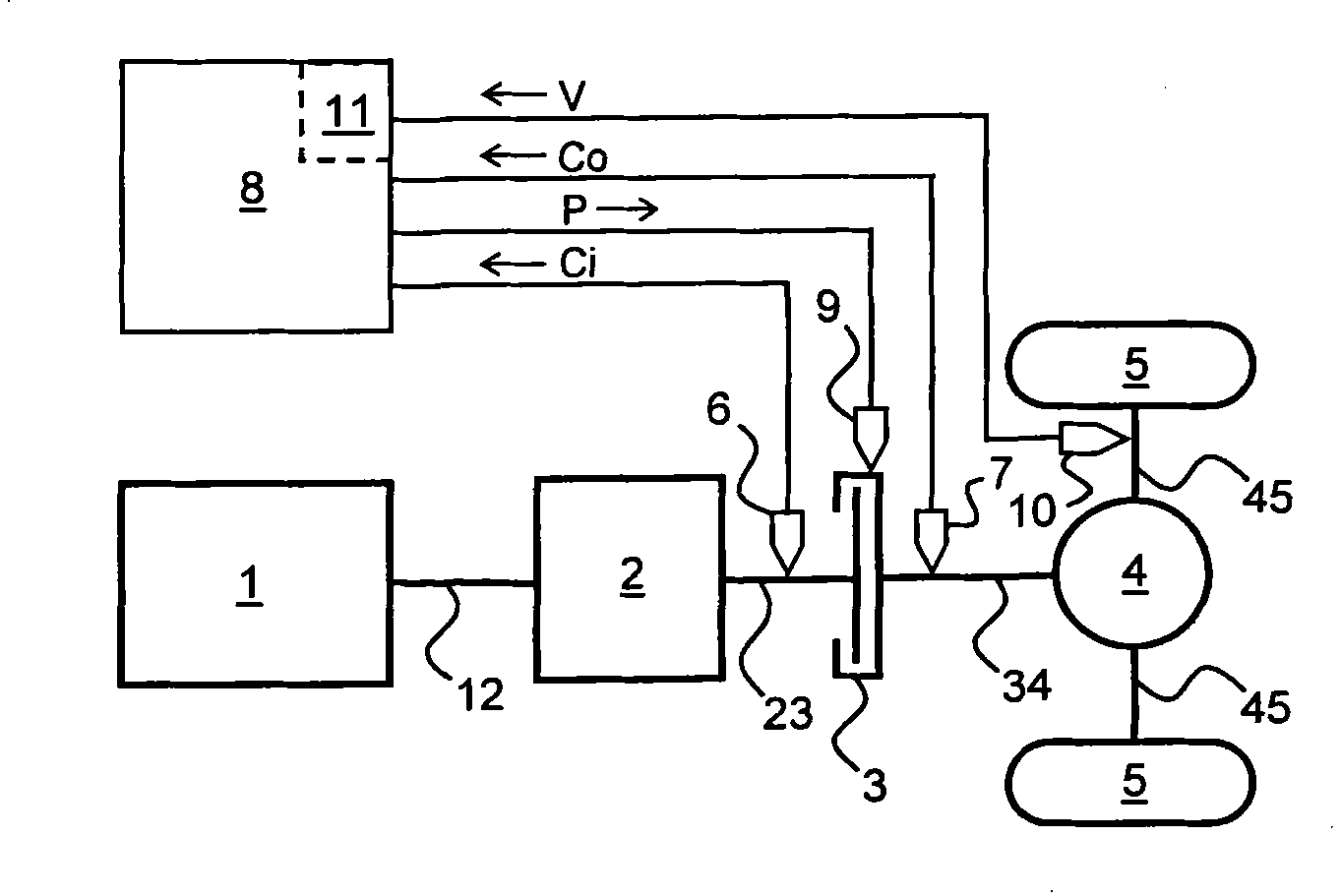
[0015] Figure 1 depicts a vehicle drive train comprising, in order (i.e., in the direction downstream of the driving force) an engine 1, a friction continuously variable transmission 2, a friction clutch 3, a final drive 4 comprising a differential transmission and two driven wheels 5. Transmission shafts 12, 23, 34 and 45 are provided between the components 1-5 of the upper drive train and are connected to them in a driving manner. Also shown schematically in FIG. 1 is a clutch slip control device comprising two rotational speed sensors 6 and 7. An Electronic Clutch Control Unit 8 or "ECCU" and a clutch actuator 9 that controls the actuation of the clutch 3 (for example, by adjusting the hydraulic clutch engagement pressure P).

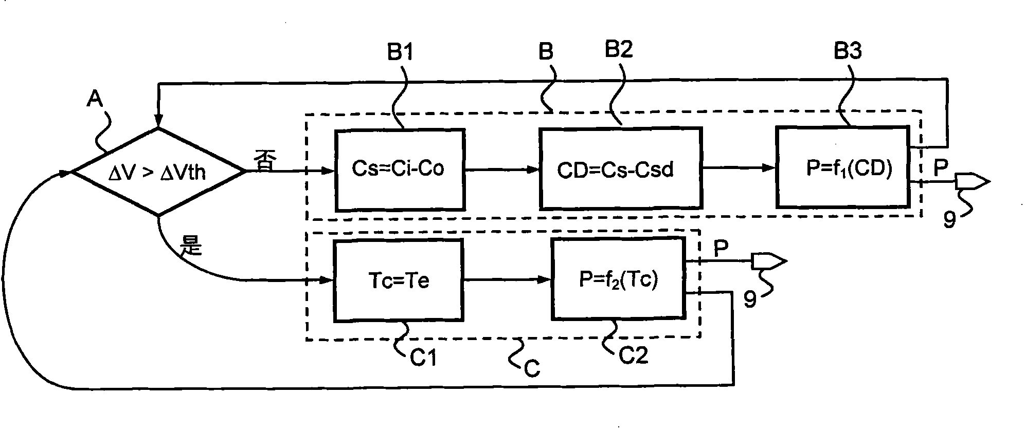
[0016] Based on this, it is known that setting and operating the ECCU 8 achieves a desired clutch slip amount Cs between the input-side speed Ci and the output-side speed Co, that is, Cs=Ci-Co. In this arrangement, when torque vibrations are introd...


PUM


Abstract

The invention relates to a method for controlling a friction clutch (3) in a vehicular drive line further provided with an engine (1), a friction-type continuously variable transmission (2) and a driven wheel (5), which method comprises the steps of controlling a slip value (Cs) of the clutch (3), of detecting the occurrence of a torque jolt (block A) and, if no such torque jolt is detected, of performing the clutch slip (Cs) control closed-loop (block B), or, if a torque jolt is detected, of performing the clutch slip (Cs) control open-loop (block C).

Description

technical field [0001] The invention relates to a method for controlling a friction clutch in a drive train of a vehicle provided with a friction continuously variable transmission. Such a control method is well known, for example in US-A-4606446 which describes a variator having two variable pulleys and a drive belt wound around the two pulleys and in frictional contact therewith. Background technique [0002] A problem commonly encountered in friction transmissions is slippage between friction components, such as between belts and pulleys, which needs to be avoided because too much slip causes excessive wear and tear on these components Or at least it can happen within a limited range. In order to prevent these slippages, a sufficient normal force is applied between these friction components, said normal force is usually determined according to the engine torque transmitted by the transmission plus a safety margin. This safety margin is introduced because the engine torq...

Claims


Application Information

Patent Timeline
Patent Type & Authority Patents(China)
IPC IPC(8): F16D48/06
CPCF16D2500/3115F16D2500/1088F16D2500/70652F16D48/06F16D2500/1045F16D2500/70252F16D2500/3065F16D2500/10412F16D2500/70426F16D2500/30406F16D2500/50293
Inventor A·A·H·M·范东恩
Owner ROBERT BOSCH GMBH
Why Eureka
Try Eureka