
Transmission mechanism utilizing permanent magnet

A transmission device and permanent magnet technology, applied in the direction of transmission device, electromechanical transmission device, electromechanical device, etc., can solve problems such as undiscovered

Inactive Publication Date: 2008-12-10
龚达明
View PDF2 Cites 6 Cited by
  • Summary
  • Abstract
  • Description
  • Claims
  • Application Information

AI Technical Summary

Problems solved by technology

The applicant has not found a device that uses permanent magnets to convert mechanical linear motion into continuous mechanical rotation

Method used


Image

  • Transmission mechanism utilizing permanent magnet
  • Transmission mechanism utilizing permanent magnet
  • Transmission mechanism utilizing permanent magnet

Examples


Embodiment Construction

[0016] The technical solution of the present application will be further described below in conjunction with the specific implementation methods shown in the drawings of the description.

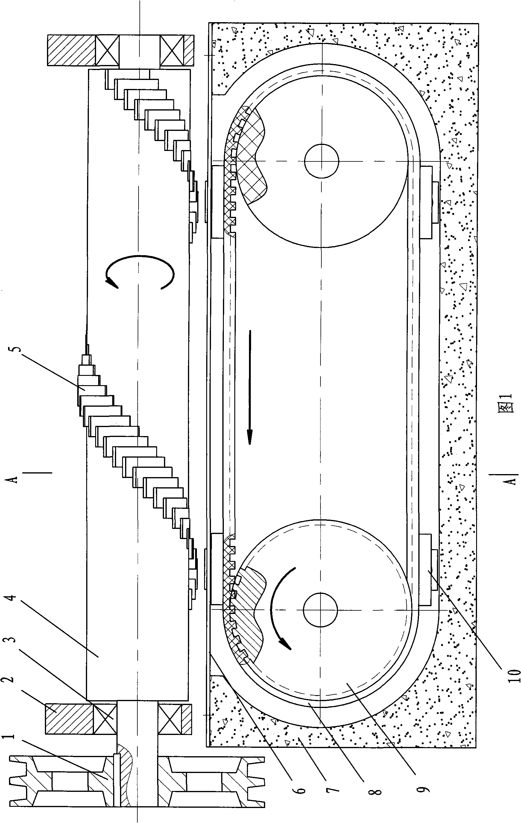
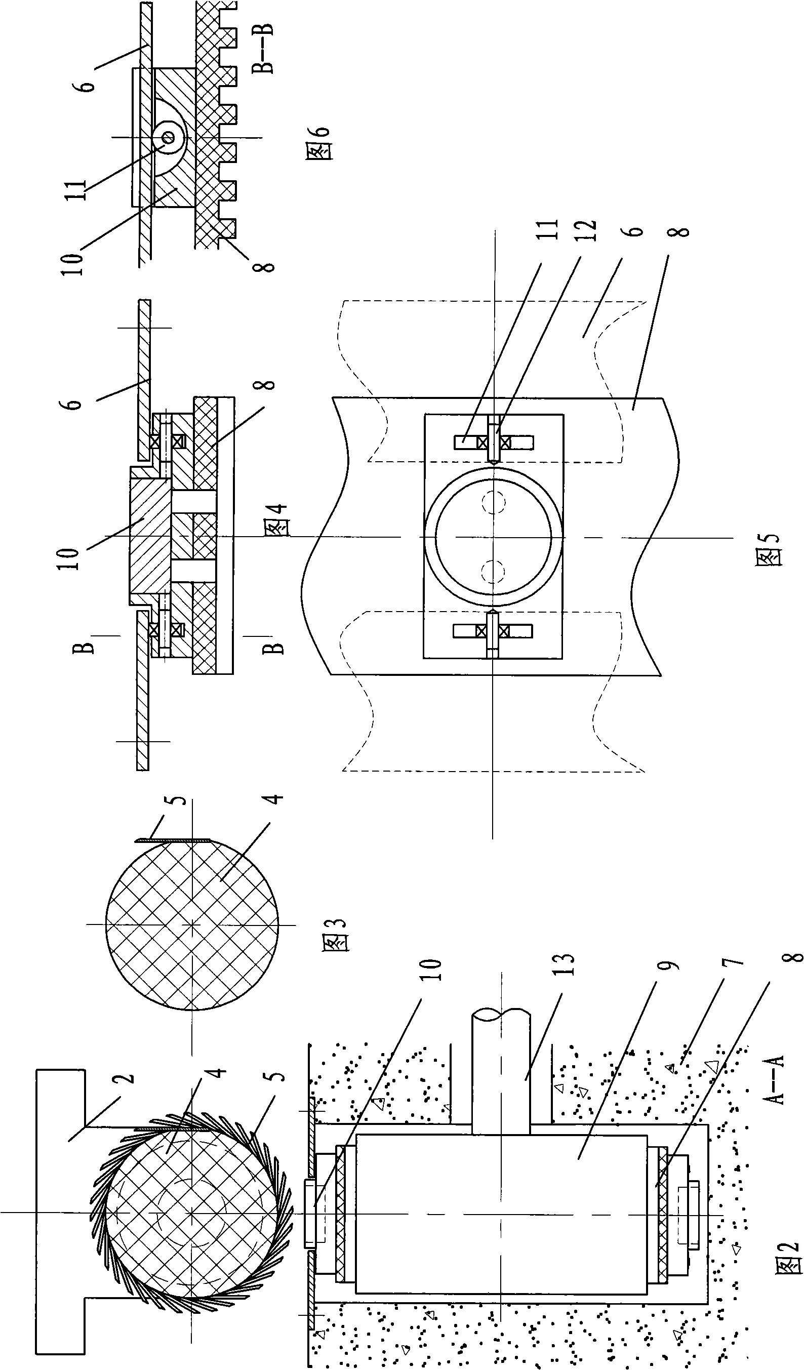
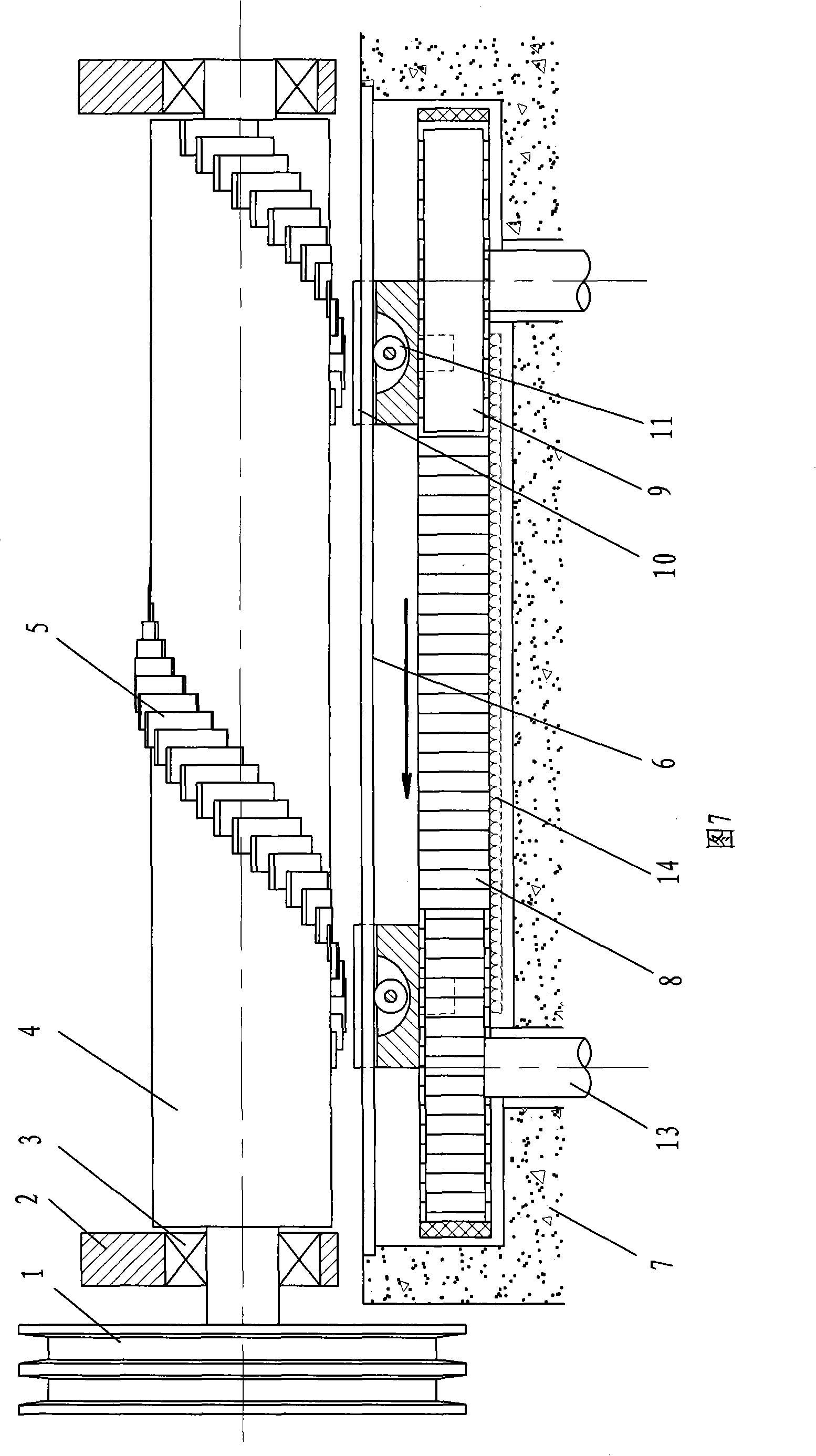
[0017] Referring to Fig. 1, it is the first embodiment of the transmission device utilizing permanent magnets, including a power output part and a drive part, wherein the power output part has a non-magnetic main shaft 4 supported on a bearing 3, and the surface of the main shaft 4 is helical in the axial direction A plurality of sucked sheets 5 are fixed in a shape; the driving part has a guide wheel 9 and a transmission belt, and the transmission belt can use a flat belt or a toothed belt. In the embodiment, the toothed belt 8 surrounds two guide wheels 9, and the two guide wheels 9 are fixed on two parallel guide wheel shafts 13 ends, and a plurality of permanent magnets 10 are directly fixed on the outer surface of the toothed belt 8, and the tooth profile in the working area The belt 8 ...


PUM


Abstract

A transmission device using a permanent magnet, belongs to the technical field of the mechanical transmission, particularly to a mechanical apparatus for converting the mechanical straight line motion into the transmission by the magnetic force of the permanent magnet, including a power output part and a power driving part, wherein the power output part has a non-magnetic principal axis supported on the bearing, the surface of the principal axis is fixed with a plurality of adsorbed sheets in the helical form axially; the driving part is provided with a guide wheel and a transmission belt towed by the outside force; a plurality of permanent magnets are fixed on the outer surface of the transmission belt; the transmission belt in the working area is parallel with the axial of the principal axis; a gap is arranged between the permanent magnet and the adsorbed sheets; the distance between the neighbor permanent magnet is equal to the helical pitch of the adsorbed sheets on the principal axis. In use, the straight line motion of the permanent magnet is converted to the rotation of the principal axis. The device is used in the mechanical technical field for changing the mechanical motion state.

Description

technical field [0001] A transmission device using permanent magnets belongs to the technical field of mechanical transmission, in particular to a mechanical device that converts mechanical linear motion into rotation by using the magnetic force of permanent magnets. Background technique [0002] In the prior art, the patent document 93105855.4 "A Permanent Magnet Magnetic Rotary Motion to Linear Reciprocating Motion Conversion Mechanism" was retrieved. The technical solution is to use the permanent magnet poles and The interaction of other disks in the same arrangement makes one or more disks rotate while pushing the disk called the moving disk to do reciprocating linear motion, realizing the transformation of the motion mode. The patent document CN2526597Y "Magnetic Transmission Device" was retrieved, and its technical solution is to transfer mechanical rotation into mechanical rotation, which is essentially equivalent to a magnetic transmission clutch. Applicants are not...

Claims


Application Information

Patent Timeline
Patent Type & Authority Applications(China)
IPC IPC(8): H02K51/00
CPCH02K49/102F16H25/2409F16H49/005H02K7/06
Inventor 龚达明
Owner 龚达明
Learn More