
Heat pipe type vacuum switch

A vacuum switch and heat pipe technology, applied in electric switches, high-voltage/high-current switches, high-voltage air circuit breakers, etc., can solve problems such as low rated current and poor heat dissipation of contacts, and achieve small evaporation and high working current , the effect of low temperature rise

Active Publication Date: 2008-12-10
INST OF ELECTRICAL ENG CHINESE ACAD OF SCI +1
View PDF4 Cites 15 Cited by
  • Summary
  • Abstract
  • Description
  • Claims
  • Application Information

AI Technical Summary

Problems solved by technology

[0006] The purpose of the present invention is to overcome the shortage of low rated current caused by the poor heat dissipation capability of the existing vacuum switch, and propose a heat pipe type vacuum switch

Method used


Image

  • Heat pipe type vacuum switch
  • Heat pipe type vacuum switch
  • Heat pipe type vacuum switch

Examples


Embodiment Construction

[0029] The present invention will be further described below in conjunction with the accompanying drawings and specific embodiments.

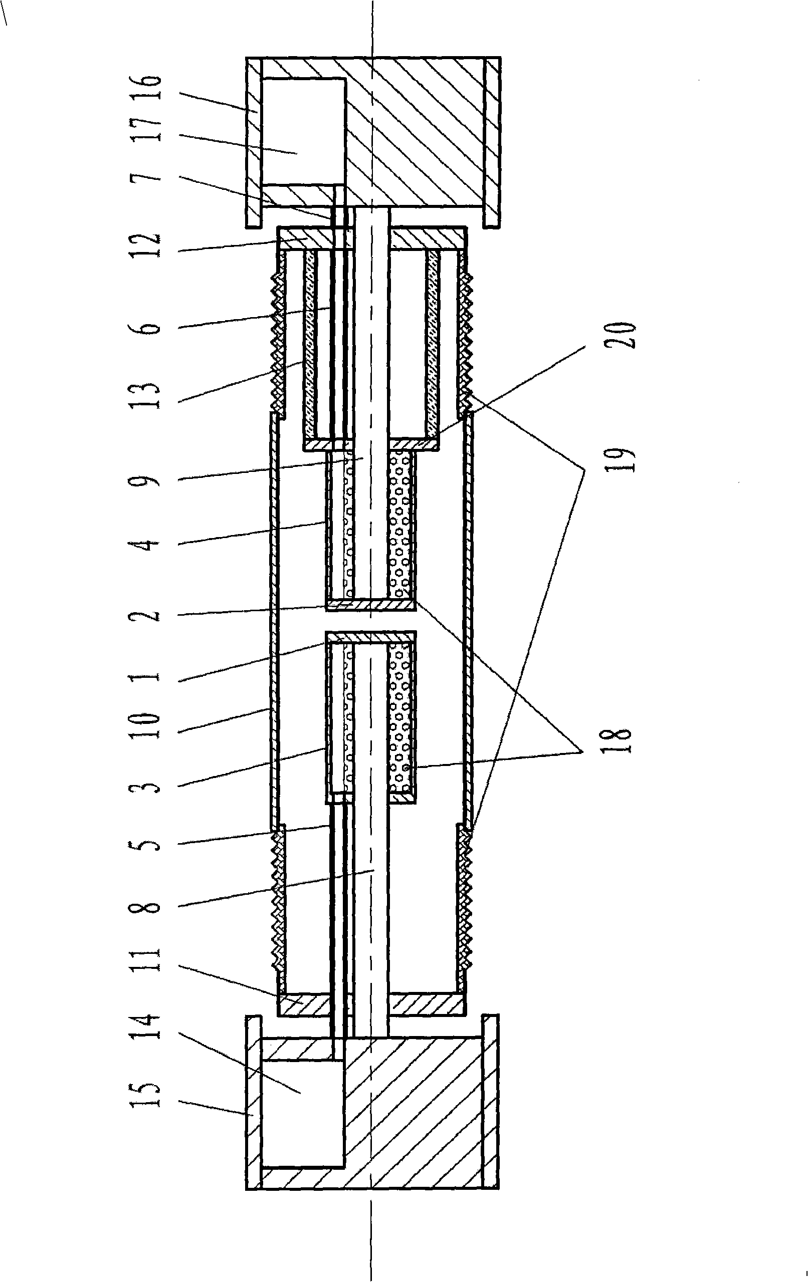
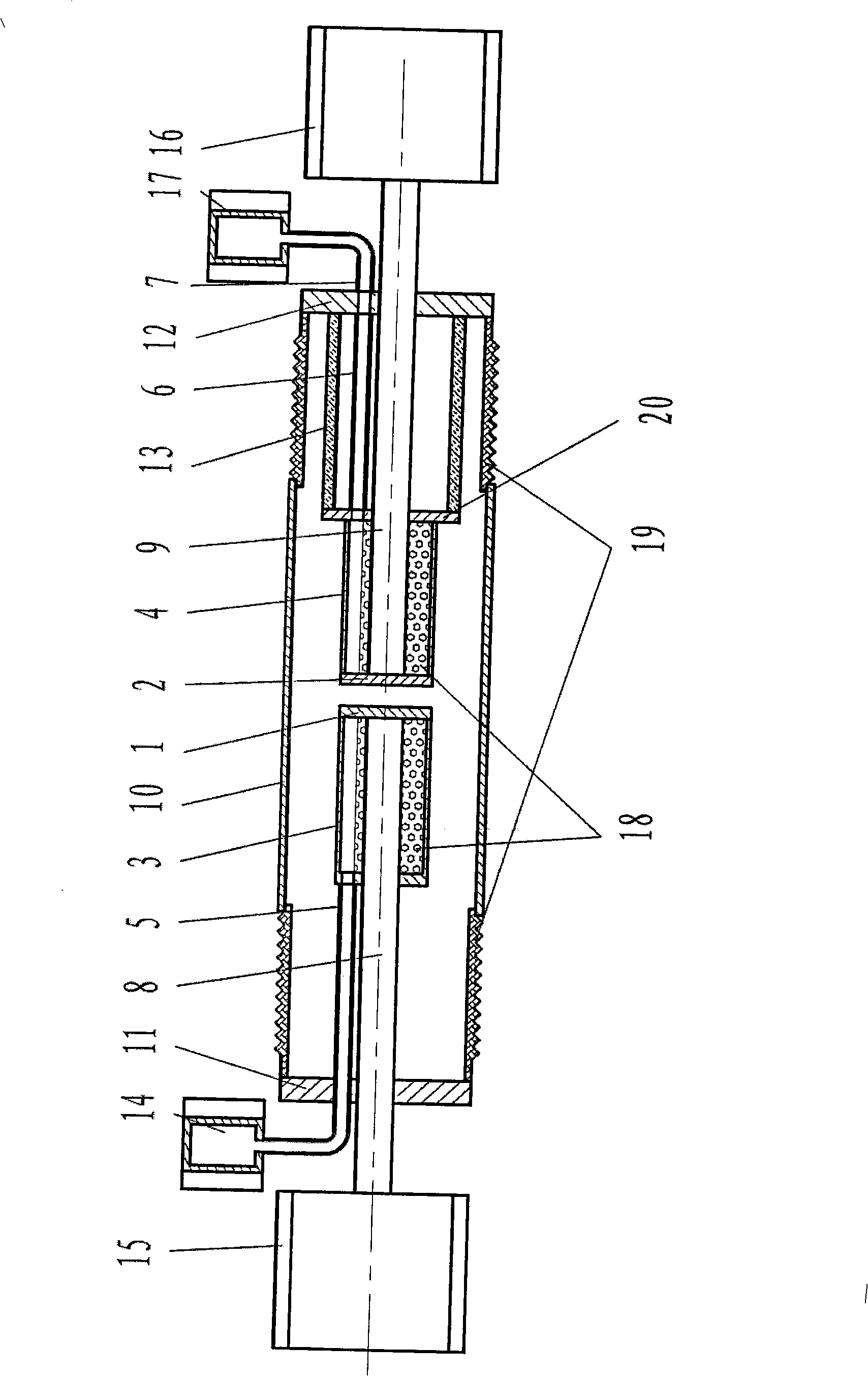
[0030] The invention is composed of dynamic and static contacts, dynamic and static conductive rods, vacuum interrupter shell, outlet terminals, heat pipe system and other parts.

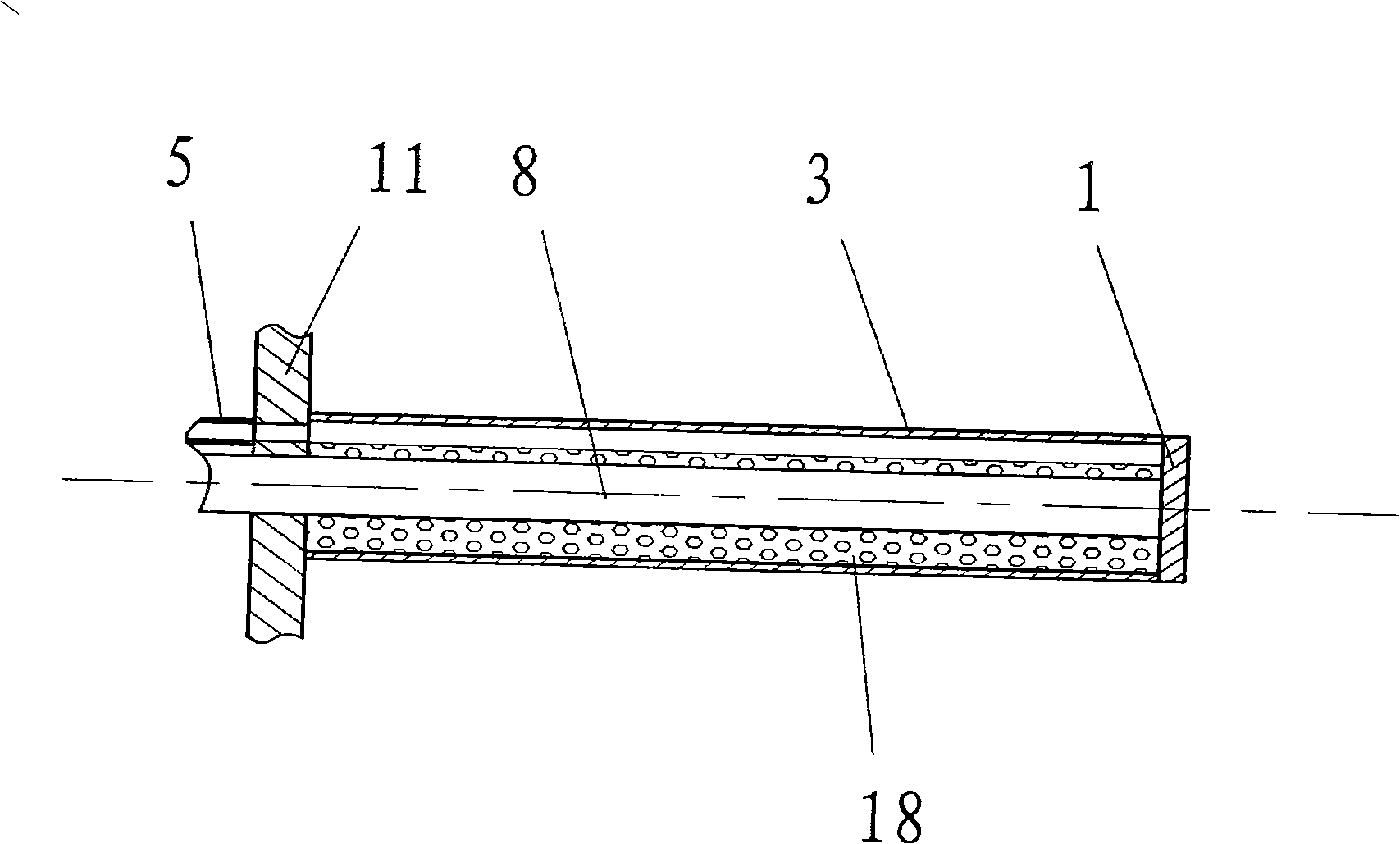
[0031] One of the specific embodiments of the present invention is as figure 1 As shown, the static end cover flange 5, the moving end cover flange 4, the shielding cover 10, and the porcelain sleeve 19 constitute the outer shell of the vacuum interrupter, which mainly play the role of mechanical support, and the shielding cover 10 also plays the role of electrical shielding. Porcelain sleeve 19 also plays an insulating role. The static contact 1, the moving contact 2, the evaporating tube 3 at the static end, and the evaporating tube 4 at the moving end are located inside the vacuum interrupter. One end of the static conductive rod 8 is connected to the static con...


PUM


Abstract

A heat pipe vacuum switch comprises a fixed contact (1), a moving contact (2), a conductive rod and a heat pipe system for cooling. The heat pipe system is comprised of an evaporating pipe, a connecting pipe and a radiator; the evaporating pipe is metallic pipe located in the vacuum arc chute and sleeved at outside of the conductive rod; the space between the evaporating pipe and the conductive rod is liquid storage space; the liquid storage space is filled with cooling liquid; the radiator is located out the vacuum arc chute and is hollow metallic cavity; the connecting pipe is metallic pipe; one end is connected with the evaporating pipe, the other end is connected with the radiator; inner cavities of the connecting pipe, the evaporating pipe and the radiator are communicated. The heat pipe system is simultaneously arranged at one side of the fixed contact (1) and one side of the moving contact (2), or is only arranged at one side of the fixed contact (1) or the moving contact (2).

Description

technical field [0001] The invention relates to a vacuum switch, in particular to a vacuum switch which adopts heat pipe cooling and is suitable for occasions with large rated current. Background technique [0002] The vacuum switches currently used in production have a vacuum switch chamber set in an insulating tube, and the surroundings of the contacts are in a high vacuum environment. The heat generated at the contacts can only be dissipated to the environment by thermal radiation and heat conduction of the conductive rod, and the heat dissipation capacity is limited. It cannot be applied to occasions with high rated current. [0003] Even if a blower is installed on the outside to enhance the heat dissipation capability of the vacuum switch to the environment, it is difficult for the heat at the contact to be transferred to the surface of the vacuum switch itself, so it has little effect on the increase of the rated current. Meanwhile, hair dryers are active, require ma...

Claims


Application Information

Patent Timeline
IPC IPC(8): H01H33/66H01H9/52H01H1/62
CPCH01H33/664H01H2009/523
Inventor 张国强邢卫军牛文豪王新
Owner INST OF ELECTRICAL ENG CHINESE ACAD OF SCI
Learn More