
Water sealing stationary ring subgroup assembling machine

An assembly machine and static ring technology, applied in the field of water seal static ring assembly assembly machines, can solve the problems of inconvenient assembly, low assembly efficiency and high difficulty, and achieve the effects of balanced and uniform force and high assembly accuracy

Active Publication Date: 2008-12-10
NINGBO VULCAN TECH CO LTD
View PDF0 Cites 21 Cited by
  • Summary
  • Abstract
  • Description
  • Claims
  • Application Information

AI Technical Summary

Problems solved by technology

[0005] 1. In the fourth step, the spring itself has a certain free height, and there is also a certain compression during assembly. The material of the elastic support itself is a soft material, which can be compressed or stretched. The spring in assembly will automatically cover the elastic support. The metal fastening ring on the top pops out, and the expected assembly effect cannot be achieved
[0006] 2. In the fifth step, when assembling the static ring friction pair, the spring must be pressed down first, and then put into the static ring friction pair. Due to the limitation of the size of the fixed shell, it is impossible to use the hands of the assembler to complete the compression of the spring , can only use a special tool to press down the spring first and then put it into the static ring friction pair, which is very inconvenient to assemble
[0007] 3. In the sixth step, when pressing down the friction pair of the static ring, the force should be appropriate and even, otherwise the friction pair of the static ring will be tilted after the installation is completed. Therefore, the requirements for the assembly workers are high and the assembly efficiency is high. Low
[0008] In summary, the manual assembly method in the prior art is difficult, low in assembly efficiency, poor in assembly accuracy, and cumbersome in operation

Method used


Image

  • Water sealing stationary ring subgroup assembling machine
  • Water sealing stationary ring subgroup assembling machine
  • Water sealing stationary ring subgroup assembling machine

Examples


Embodiment Construction

[0040] The assembly machine of the water-sealed static ring assembly of the present invention will be further described below in conjunction with the drawings and specific embodiments. In the drawings, the left side is left, and the right side is right.

[0041] Such as image 3 As shown, the water seal static ring assembly machine of the present invention mainly consists of a base plate 13, a workbench 12, a guide rail 32, an indenter device 1, a pressing plate device, a sliding plate device, and a mechanical device used in cooperation with the pressing plate device and the sliding plate device. Claw composition; described workbench 12 is installed and fixed on the base plate 13, described pressure head device 1 is installed and fixed on the left end of base plate 13, and described pressure plate device is located at the bottom of pressure head device 1 and is installed and fixed on the base plate 13, The axis of the through hole 17 of its platen device and the axis of the pr...


PUM


Abstract

The invention discloses an assembly machine for water seal static ring components, which mainly comprises a bottom plate (13), a worktable (12), a lead rail (32), an indenter device I, a pressure plate device, a slide carriage device and mechanical grippers matched with the pressure plate device and the slide carriage device; the worktable (12) is arranged above the bottom plate (13); the indenter device I is arranged at one end of the bottom plate (13); the pressure plate device is arranged below the indenter device I and is also arranged on the bottom plate (13); the axis of a through hole (17) of the pressure plate device and the axis of an indenter I (15) of the indenter device I are in the same line; the minimum diameter of the through hole (17) is larger than the external diameter of the indenter I (15); the slide carriage device is matched with the lead rails (32) arranged on the bottom plate (13) in a sliding way. The assembly machine for water seal static ring components is high in assembly precision and efficiency, simple and convenient in operation.

Description

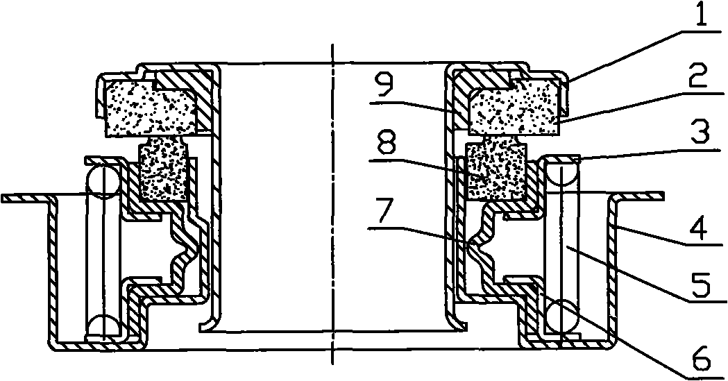
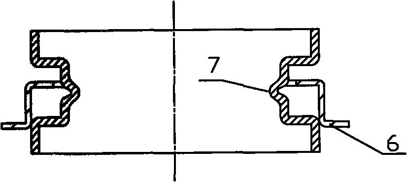
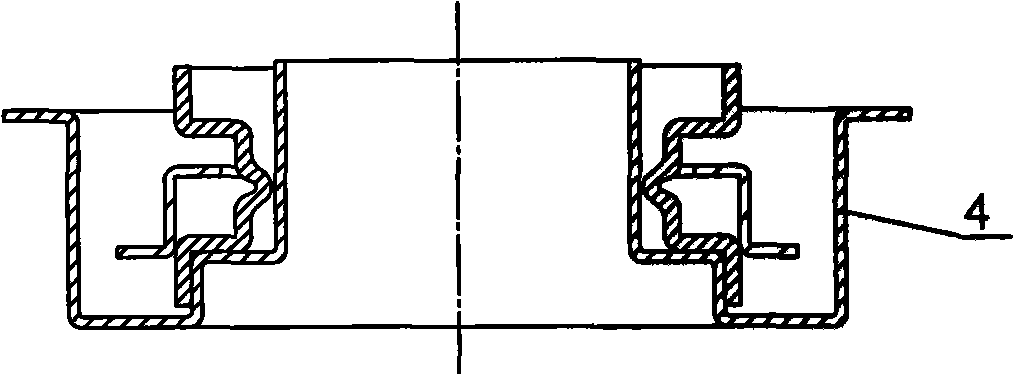
technical field [0001] The invention relates to an assembly device, in particular to an assembly machine for water-sealed static ring components. Background technique [0002] At present, common water seal structures such as figure 1 As shown, it is mainly used in the automobile industry. It generally includes a moving ring assembly and a static ring assembly. The two are connected through a flanging assembly process to form a whole; the moving ring assembly includes a shaft sleeve 1, a rubber sealing ring 9 and a moving ring The friction pair 2; the shaft sleeve 1 and the dynamic ring friction pair 2 use the interference fit of the rubber sealing ring 9 to play a sealing role; the static ring assembly includes a fixed shell, a spring, two metal fastening rings, a static ring friction pair and an elastic Bracket; the lower end of the elastic bracket is interference fit with the boss of the fixed shell through a metal fastening ring; the upper end of the elastic bracket is i...

Claims


Application Information

Patent Timeline
Patent Type & Authority Applications(China)
IPC IPC(8): B23P21/00B23P19/027
Inventor 邬国平
Owner NINGBO VULCAN TECH CO LTD
Learn More