
Hole drilling calibration method for printed circuit board

A printed circuit board and positioning technology, which is applied in the direction of printed circuit, printed circuit manufacturing, electrical components, etc., can solve the problems of affecting the level of the substrate, the inability of the drilling machine to drill accurately, and the gap error, etc., to improve the accuracy of drilling degree of effect

Active Publication Date: 2008-12-03
CIN PHOWN TECH
View PDF0 Cites 18 Cited by
  • Summary
  • Abstract
  • Description
  • Claims
  • Application Information

AI Technical Summary

Problems solved by technology

[0004] The above-mentioned method of using positioning pins to correct the level of the substrate, when the substrate is placed on the bed, is likely to produce a gap error between the positioning pin and the clamping groove, which will affect the level of the substrate, resulting in the problem that the drilling machine cannot drill holes accurately At the same time, the above-mentioned method of using the positioning column to cooperate with the tool table to correct the alignment of the substrate also has the problem of gap error between the positioning column of the tool table and the clamping groove, and also has the positioning of the positioning column of the substrate and the tool table. There is a gap error problem between the holes, so it needs to be improved urgently

Method used


Image

  • Hole drilling calibration method for printed circuit board
  • Hole drilling calibration method for printed circuit board
  • Hole drilling calibration method for printed circuit board

Examples


Embodiment Construction

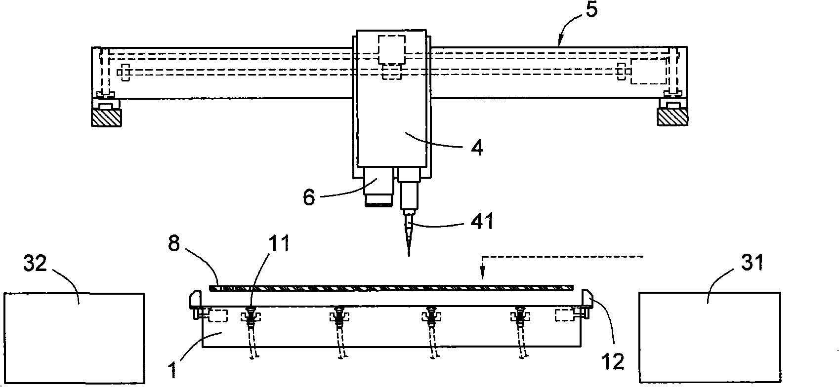
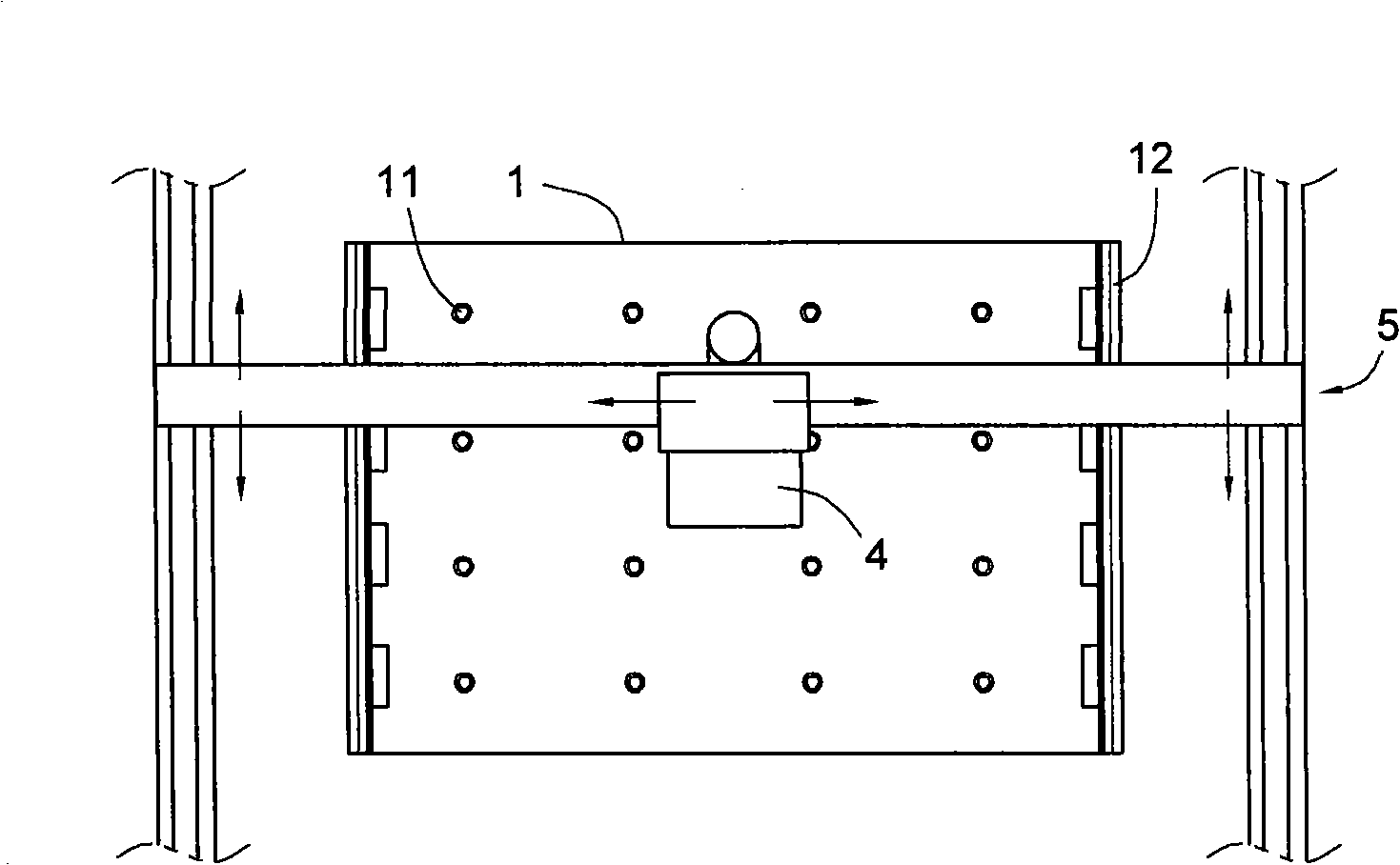
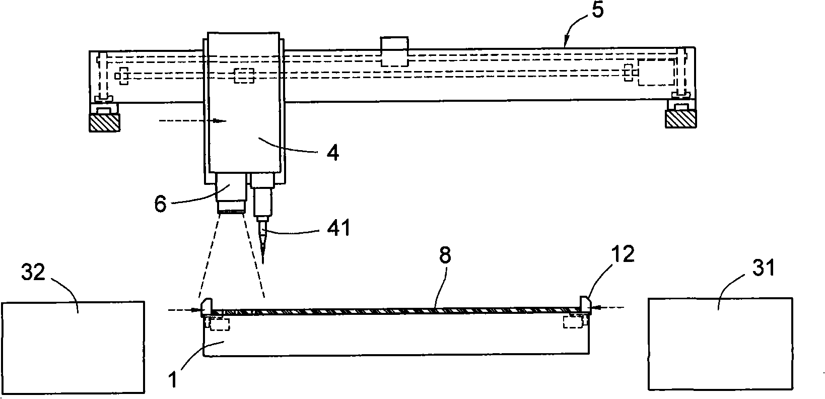
[0030] first as figure 1 As shown, it discloses a schematic configuration diagram of the implementation environment of the first embodiment of the printed circuit board drilling alignment method of the present invention, and cooperates with figure 2 and image 3 Illustrate that the implementation environment of the present invention includes:

[0031] A bed 1, interposed between a discharge device 31 and a receiving device 32, the discharge device 31 can transfer the substrate 8 to the bed 1, and the receiving device 32 can pick up the substrate 8 on the bed 1 , to transfer to the subsequent processing area station, and the bed 1 has a plurality of negative pressure holes 11 capable of adsorbing the positioning of the substrate 8, a set of corresponding clamps 12 or a clamping groove capable of clamping the positioning of the substrate 8;

[0032] A drilling machine 4 is slidably arranged on the top of the bed platform 1, and can be driven by a drilling machine driving devi...


PUM


Abstract

The invention relates to a drill aligning method of a printed circuit board, which comprises a substrate that comprises at least three target points which is positioned by a machine bed; a visual imaging machine arranged above the machine bed is used for reading each target point on the substrate; a target point benchmark value loaded in the visual imaging machine is used for comparison to calculate and obtain an error value; meanwhile, the machine bed or a drilling machine arranged above the machine bed is driven to compensate displacement according to the error value so as to adjust the quasi-position between the drilling machine and the substrate to drill according to the quasi-position and enhance the precision of the drilling of the substrate.

Description

technical field [0001] The invention relates to a calibration method for drilling a printed circuit board, in particular to a method for correcting the alignment between a printed circuit board and a drilling blade before drilling a printed circuit board. Background technique [0002] Printed circuit board (PCB, hereinafter referred to as substrate) must first drill at least three positioning holes (Tooling holes) on the substrate or make at least three optical points through the exposure process before drilling parts holes for soldering electronic components. , the positioning hole and the optical point are collectively referred to as the target point, which can be used to correct the alignment between the substrate and the drilling blade. The drilling blade is a drilling machine with a fine drill bit. [0003] The above-mentioned method of using the target point to correct the substrate level is traditionally to respectively perforate a positioning column in each positioni...

Claims


Application Information

Patent Timeline
Patent Type & Authority Applications(China)
IPC IPC(8): H05K3/00H05K13/08
Inventor 姚志金
Owner CIN PHOWN TECH
Learn More