Energy-saving frying oven and its control method

A frying furnace and hob technology, which is applied in the field of automatic control frying furnace and its control, can solve problems such as wasting time, increasing air pollution, and poor operating environment for personnel, so as to achieve a comfortable operating environment, eliminate fire hazards, and eliminate fire hazards Effect

Inactive Publication Date: 2008-10-15
孟仁华
View PDF0 Cites 5 Cited by
  • Summary
  • Abstract
  • Description
  • Claims
  • Application Information

AI Technical Summary

Problems solved by technology

The traditional method adopts manual ignition, manual control of gas on and off, each ignition must close the air valve, re-adjust the air valve, air valve
In the actual operation process, this kind of operation is extremely inconvenient and wastes time. In order to avoid extinguishing the fire and readjusting the fire, the operator seldom adjusts or does not adjust the ratio of wind and gas during use, resulting in empty fire.
In addition, because the frying pan is not on the flame due to feeding, washing the pan, and serving vegetables, it also leads to the empty fire of the stove, resulting in unnecessary waste, which greatly increases the production cost of the catering industry, and the scarce and limited energy is consumed for no reason. The emission of combustion exhaust gas increases the pollution of the atmosphere, and the air combustion of the fire also buryes fire hazards. Countless fires occur every year because of this, and the operating environment of personnel is relatively bad, which affects the quality of work.

Method used


Image

  • Energy-saving frying oven and its control method
  • Energy-saving frying oven and its control method
  • Energy-saving frying oven and its control method

Examples


Embodiment 1

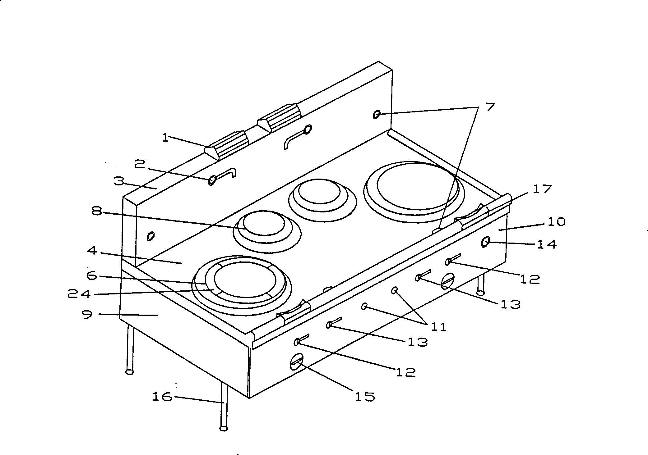
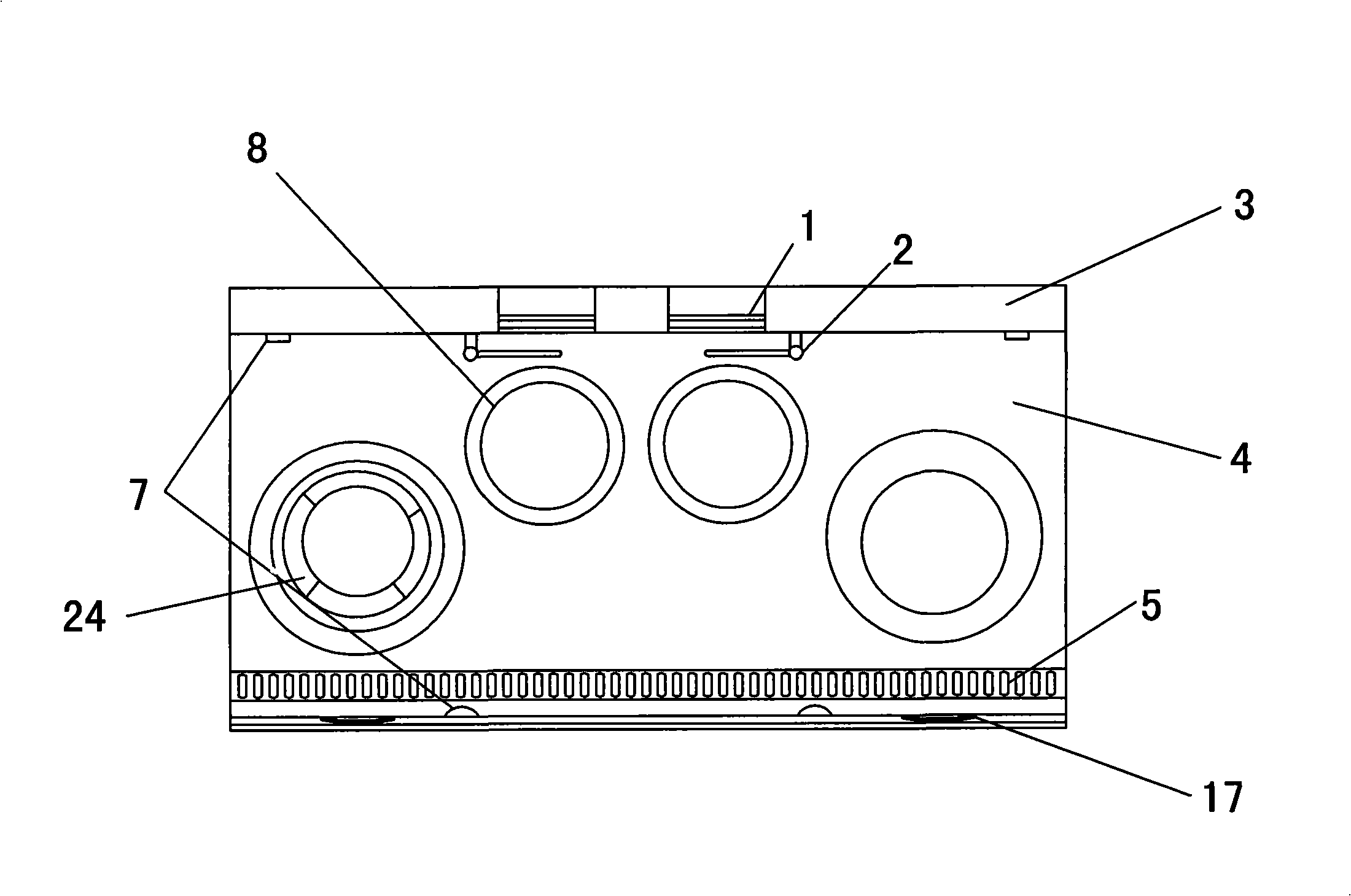
[0020] Such as Figure 1 to Figure 6 As shown, the present invention is an energy-saving frying furnace, the device includes a hob and an adjusting leg 16 supporting the hob, and the frying oven also includes a water supply part, an air supply part, a combustion part and an electric control part, wherein the water supply part includes The water inlet pipe installed on the right front of the frying furnace, the water inlet pipe is connected to the water valve 14 of the G1 / 2" gate valve, and connected to the swing faucet 2 through the bottom and back of the hob. The hob contains a back plate 3. The swing faucet 2 is installed on the backboard 3, the top of the backboard 3 is also installed with the flue gas 1 of the combustion exhaust gas; The valve 15 is connected to the burner of the combustion part through the air pipe 21. The blower adopts an outsourced 220V low-noise medium-pressure fan. The burner is composed of a nozzle 26, a gas distributor 27, a double-needle ignition n...


PUM


Abstract

The invention relates to an energy saving frying stove and a method for controlling the same, belonging to the commercial kitchenware technical field. The device in the invention comprises a stove frame and an adjusting leg supporting the stove frame, and further comprises a water supply part, an air supply part, a combustion part and an electronic control part, wherein a blower and an air valve of the air supply part are connected with the combustion part through an air duct; the electronic control part is positioned inside the stove frame and comprises a photoelectric switch which is used for monitoring the working of a frying pan. The stove frame comprises a table surface on which a hearth is arranged. The photoelectric switch is arranged on the table surface and a back plate of the stove frame. The diagonal line formed by the photoelectric switch traverses the hearth. The electronic control part is controllably connected with the combustion part through a signal of the photoelectric switch. The frying stove is ignited and extinguished to carry out circular work by the photoelectric switch which monitors the working status of the frying stove and sends the signal back to a control circuit. Accordingly, the production cost is effectively reduced, the energy is saved, exhaust emission is reduced, and fire dangers are eliminated.

Description

technical field [0001] The invention relates to an automatic control frying furnace and a control method thereof, belonging to the technical field of commercial kitchen utensils. Background technique [0002] Frying furnaces mainly involve hotels, guesthouses, catering companies, staff canteens and centralized dining kitchens. The combustion and control methods of the traditional frying furnace are as follows: first, turn on the power switch, adjust the air valve to the maximum, blow off the residual gas and exhaust gas in the burner, and close the air valve; Ignite the flame, open the fire valve, slightly open the air valve, open the main air valve, ignite the main air, open the large air valve, and then open the large main air valve. Putting the pan to stir-fry, if the wind and gas are adjusted to the maximum at one time, the fire will be blown out, and the main gas will be too large to cause deflagration. The traditional method adopts manual ignition, manual control of ...

Claims


Application Information

Patent Timeline
Patent Type & Authority Applications(China)
IPC IPC(8): F24C3/00F24C3/10F24C3/12F24C15/00
CPCY02B40/166Y02B40/00
Inventor 孟仁华
Owner 孟仁华
Why Eureka
Try Eureka