
Electronic paper laser cutting process

A cutting method and laser cutting technology, applied in laser welding equipment, welding equipment, metal processing equipment, etc., can solve the problems of electronic paper abnormalities, easy to have bright spots in electronic paper, and reduce the quality of materials, so as to improve the quality rate effect

Inactive Publication Date: 2008-10-15
陈锡富
View PDF0 Cites 9 Cited by
  • Summary
  • Abstract
  • Description
  • Claims
  • Application Information

AI Technical Summary

Problems solved by technology

[0004] However, flexible displays, such as electronic paper (e-paper), are made of flexible materials. When cutting and cutting with a metal die, the e-paper will be squeezed at the cutting line (or cutting surface). When using 40 The quality of the electronic paper after cutting and cutting is magnified by an electron microscope with a magnification of 1.5 times. It can be clearly found that the edge of the electronic paper after cutting is warped, and the cut edge is not a flat edge, which makes the electronic paper prone to distortion when displayed. Bright spots are generated, resulting in poor image quality
In addition, when cutting with a metal knife mold, the metal knife mold must be selected, and a mold must be set up. When cutting, parameters need to be adjusted, and a long time course for cutting stability is required, so the cost is relatively high.
Furthermore, when the cutting die is a metal blade, during the process of cutting the e-paper, there will be static electricity between the metal and the e-paper, which will easily cause the electrical abnormality of the e-paper.
[0005] According to the above, using a metal die to cut electronic paper will cause damage to the material itself and reduce the quality of the material, and when cutting, the power used is high, so the process cost is high

Method used


Image

  • Electronic paper laser cutting process
  • Electronic paper laser cutting process
  • Electronic paper laser cutting process

Examples


Embodiment Construction

[0027] The invention discloses a laser cutting method for electronic paper, aiming at increasing the yield and quality of electronic paper after cutting and reducing the process cost by laser cutting and matching with a cutting jig with a cooling device.

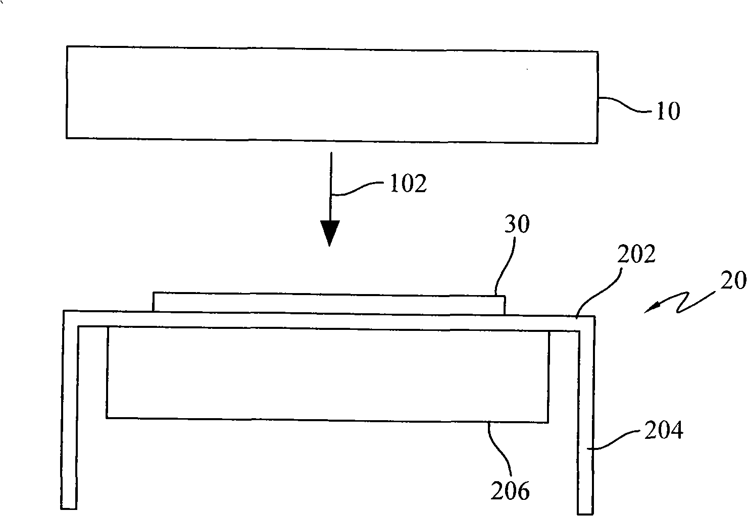
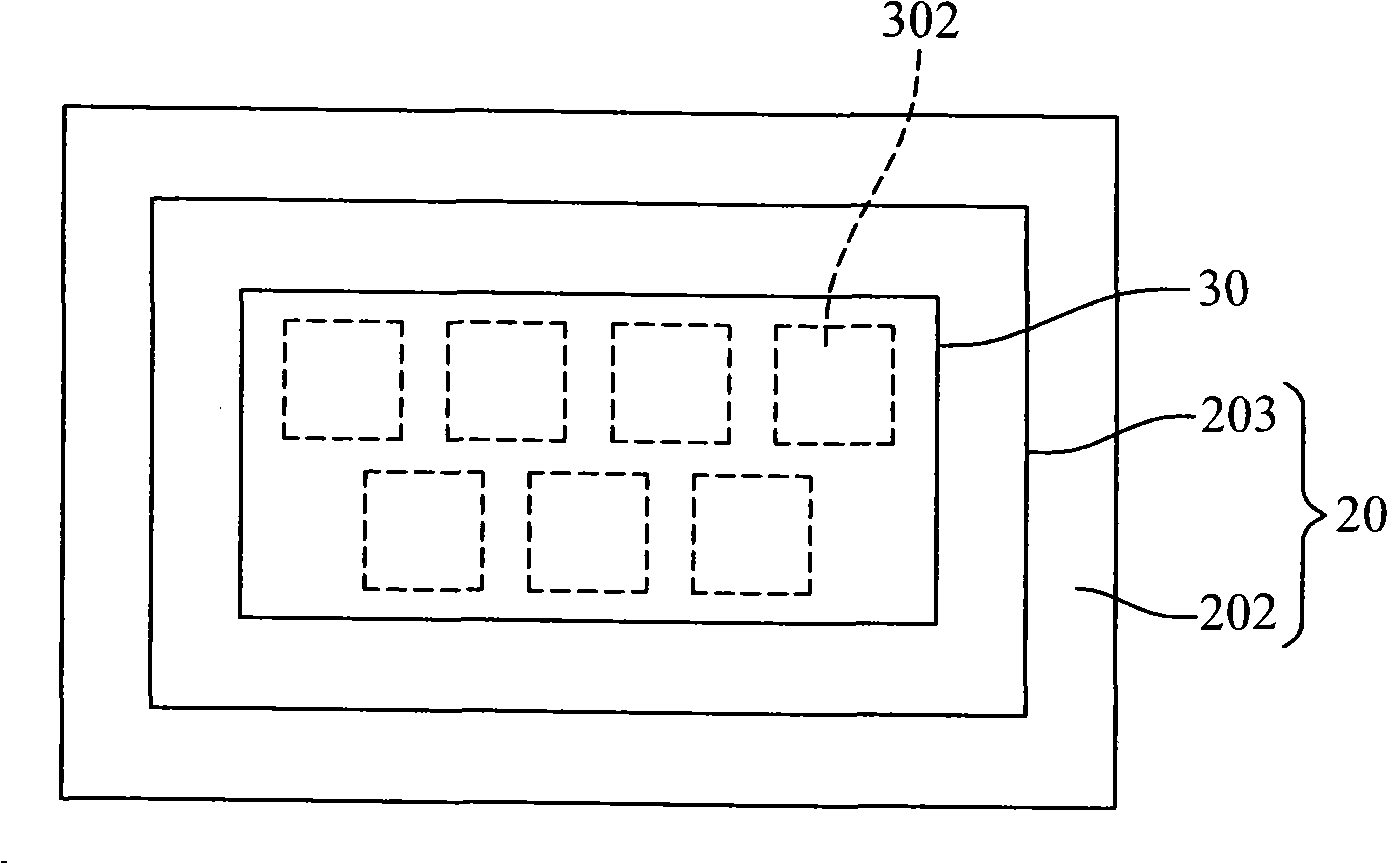
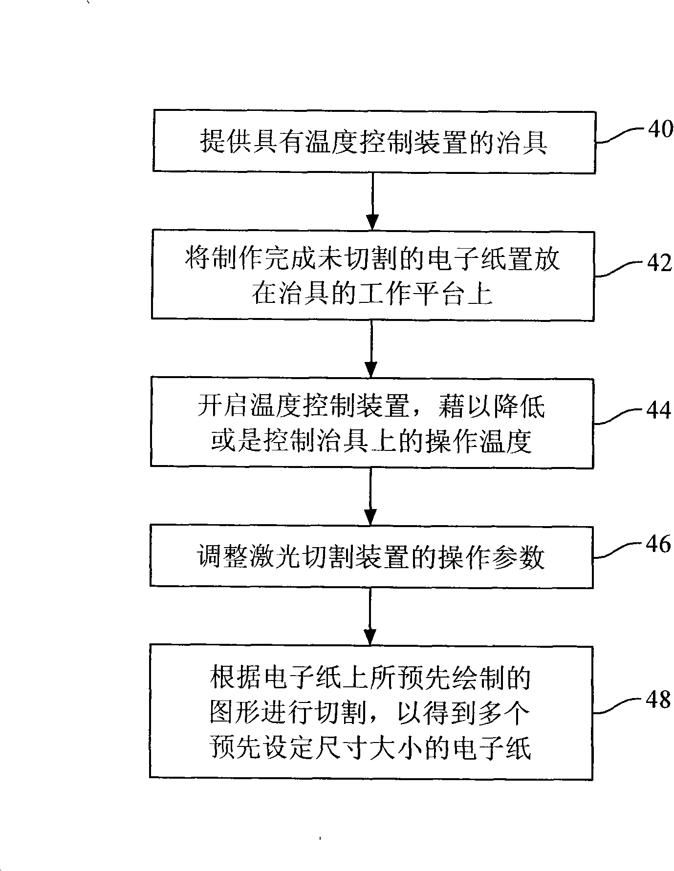
[0028] Figure 1 to Figure 2 It is a schematic diagram of the device according to the electronic paper laser cutting method disclosed in the present invention. image 3 It is a flow chart of the steps of the electronic paper laser cutting method disclosed in the present invention.

[0029] First, please refer to figure 1 , which represents a schematic diagram of the device of the electronic paper laser cutting method disclosed in the present invention. The mark 10 is a laser cutting device. Here, the laser cutting device 10 is a commonly used laser cutting device, which can be applied to the cutting process of electronic paper without special improvement or design. Here, it is worth mentioning that if a reflective device ...


PUM


Abstract

The invention provides a method for cutting electronic paper by using laser and aims to cut the electronic paper with high qualification rate and quality by utilizing laser cutting in coordination with a jig with a temperature controlling device. The method comprises the steps of providing a jig with a temperature controlling device; putting finished but uncut electronic paper on the platform of the jig, wherein the electronic paper has pre-designed cutting patterns; starting the temperature controlling device inside the jig to control or reduce the heat generated during operation; adjusting operating parameters of a laser cutting device; and cutting the patterns to be cut on the electronic paper to get electronic paper with pre-designed size.

Description

technical field [0001] The present invention relates to an electronic paper cutting method, more particularly a laser cutting method for electronic paper. Background technique [0002] The great advances in display technology have stimulated consumers' strong demand for audio-visual products. Regardless of TVs, mobile phones, or personal digital assistants such as PDAs (Personal Digital Assistants), the trend of increasing screen size is becoming more and more obvious. However, the volume and weight It seems to be always proportional, the larger the screen, the less likely it is to be light. However, with the rise of flexible displays, the above-mentioned dilemma has found a solution. The lightness and flexibility of flexible displays not only eliminates the development bottleneck of displays in the past, but also expands unlimited application space in one fell swoop. [0003] Nowadays, because network communication is combined with mobile phones, notebook computers or pers...

Claims


Application Information

Patent Timeline
Patent Type & Authority Applications(China)
IPC IPC(8): B23K26/00B23K26/42B23K26/38B23K26/70
Inventor 陈锡富
Owner 陈锡富
Learn More