Fuel supply system component protective construction
一种燃料供应系统、保护结构的技术,应用在装料系统、车辆部件、燃料喷射泵等方向,能够解决难保护滤油器、损坏滤油器等问题
- Summary
- Abstract
- Description
- Claims
- Application Information
AI Technical Summary
Problems solved by technology
Method used
Image
Examples
Embodiment approach 1
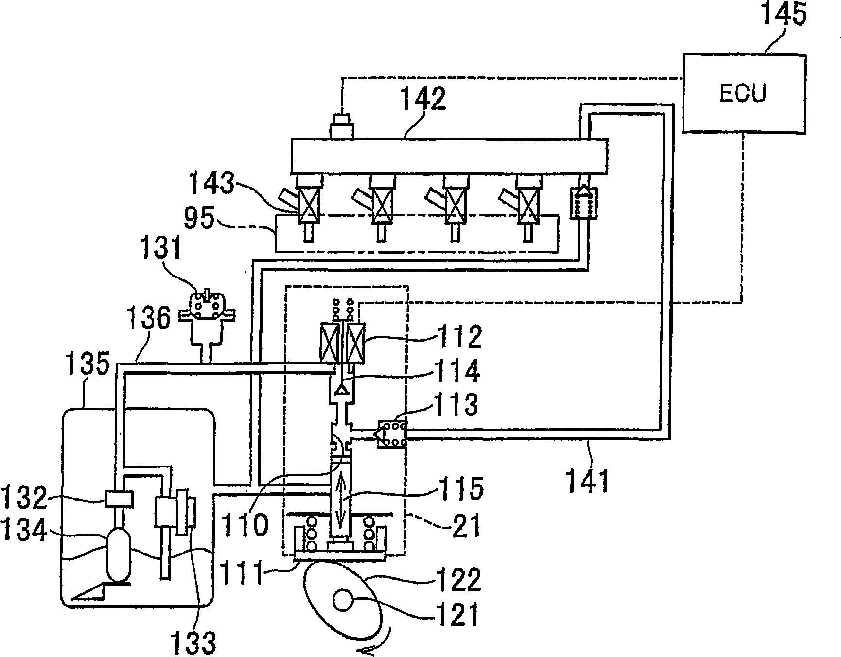
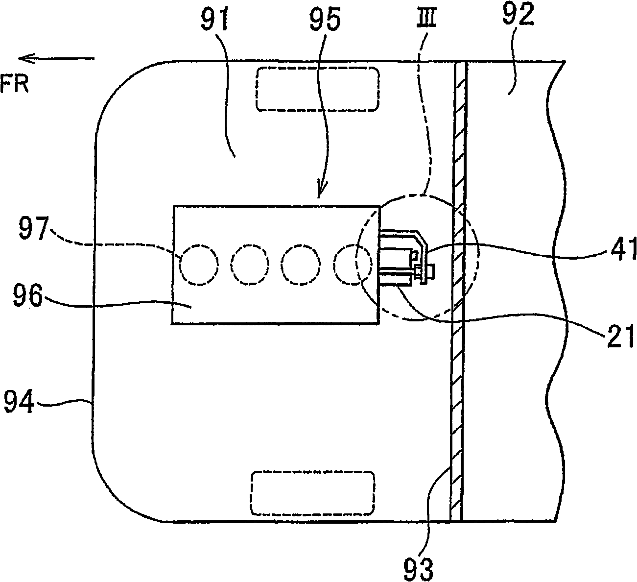
[0034] figure 1 It is a block diagram showing a fuel supply system mounted on a vehicle. refer to figure 1 , this vehicle includes an in-cylinder direct injection engine 95 in which fuel that has been pressurized to a high pressure is directly injected into a fuel chamber of a cylinder. This fuel supply system includes a fuel tank 135, a high-pressure fuel pump 21, an accumulator pipe 142 (transfer pipe or common rail, etc.), an injector 143, and the like.
[0035] The high-pressure fuel pump 21 is connected to the fuel tank 135 and the accumulator pipe 142 through the low-pressure fuel passage 136 and the high-pressure fuel passage 141 , respectively. The pulsation damper 131 is disposed on the low-pressure fuel passage 136 to reduce fuel pulsation. A low-pressure fuel pump 134 , an oil filter 132 , and a pressure regulator 133 are disposed within the fuel tank 135 .
[0036] The high-pressure fuel pump 21 fulfills the role of pressurizing fuel to a high pressure and delive...
Embodiment approach 2
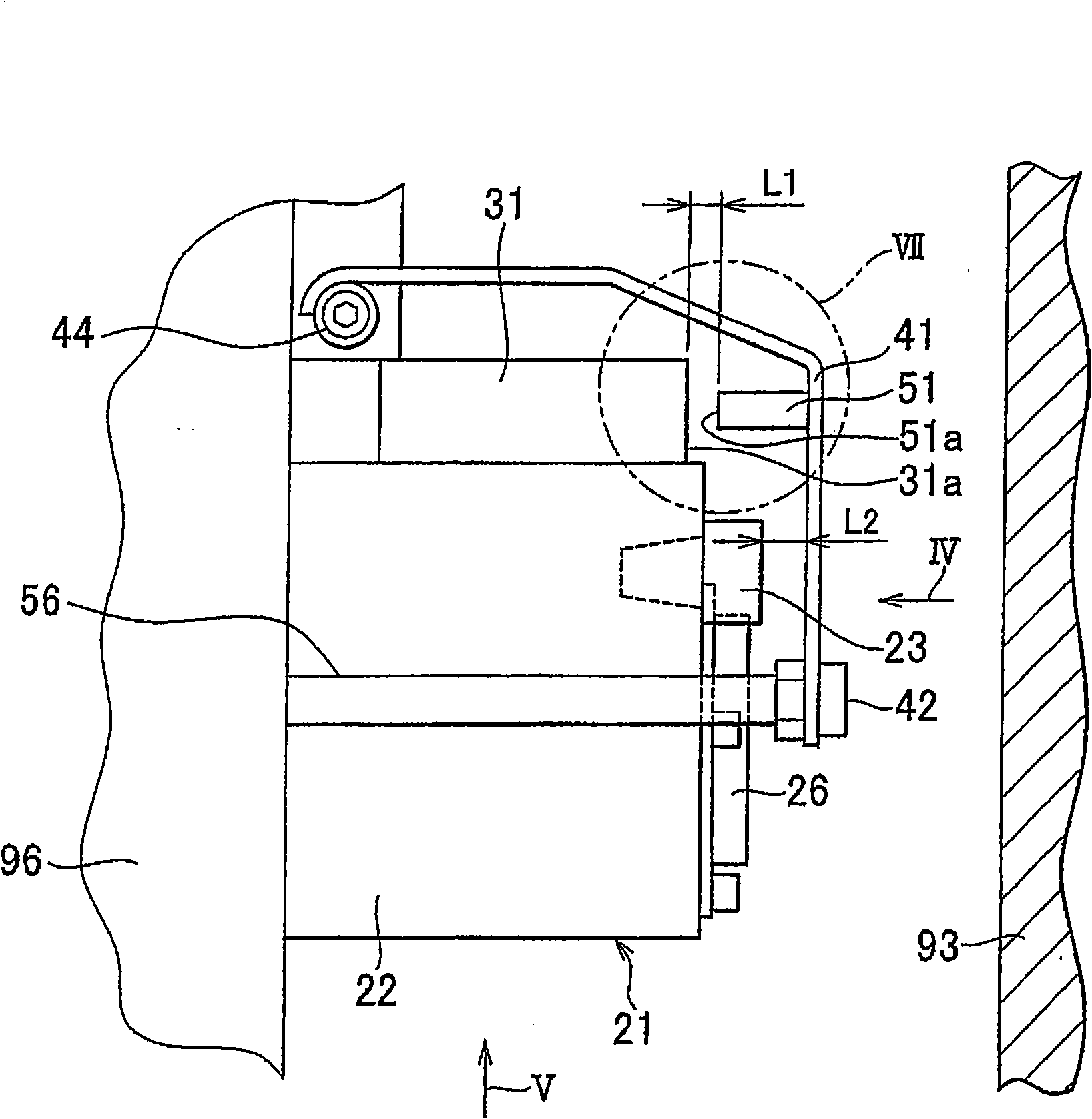
[0070] Figure 8 is a rear view showing the inside of a vehicle engine room to which a protection structure for fuel supply system components according to a second embodiment of the present invention is applied. and, Figure 9 yes Figure 8 Side view of the engine compartment in . Figure 8 is corresponding to the first embodiment Figure 4 view of the Figure 9 is corresponding to the first embodiment Figure 5 view. Comparing the protection structure of fuel supply system components according to this embodiment with the protection structure of fuel supply system components according to the first embodiment, they basically have the same configuration. Hereinafter, repeated explanations will not be given for repeated features of the configuration.
[0071] refer to Figure 8 and Figure 9 , the high-pressure fuel pump 21 further includes a covering member 26 fixed to the main body portion 22 . This covering member 26 closes the opening portion formed in the main body...
Embodiment approach 3
[0080] Figure 10 is a plan view showing the interior of a vehicle engine room to which a protection structure for fuel supply system components according to a third embodiment of the present invention is applied. Figure 10 is corresponding to the first embodiment image 3 view. Comparing the protection structure of fuel supply system components according to this embodiment with the protection structure of fuel supply system components according to the first embodiment, they basically have the same configuration. Hereinafter, repeated explanations will not be given for repeated features of the configuration.
[0081] refer to Figure 10 , in this embodiment, the pin member 81 replaces the image 3 A pin member 51 is provided between the protector 41 and the block 31 as a shock absorbing member. This pin member 81 is provided at a position spaced apart from both the protector 41 and the block 31 . The pin member 81 is supported between the protector 41 and the block 31 b...
PUM
 Abstract
Description
Claims
Application Information
 - Generate Ideas
- Intellectual Property
- Life Sciences
- Materials
- Tech Scout
- Unparalleled Data Quality
- Higher Quality Content
- 60% Fewer Hallucinations
Browse by: Latest US Patents, China's latest patents, Technical Efficacy Thesaurus, Application Domain, Technology Topic, Popular Technical Reports.
© 2025 PatSnap. All rights reserved.Legal|Privacy policy|Modern Slavery Act Transparency Statement|Sitemap|About US| Contact US: help@patsnap.com


