Respiration suppressing mat and magnetic resonance imaging apparatus and method
A technology of magnetic resonance imaging and respiratory depression, applied in magnetic resonance measurement, medical science, surgery, etc., can solve problems such as dyspnea
- Summary
- Abstract
- Description
- Claims
- Application Information
AI Technical Summary
Problems solved by technology
Method used
Image
Examples
no. 1 Embodiment approach
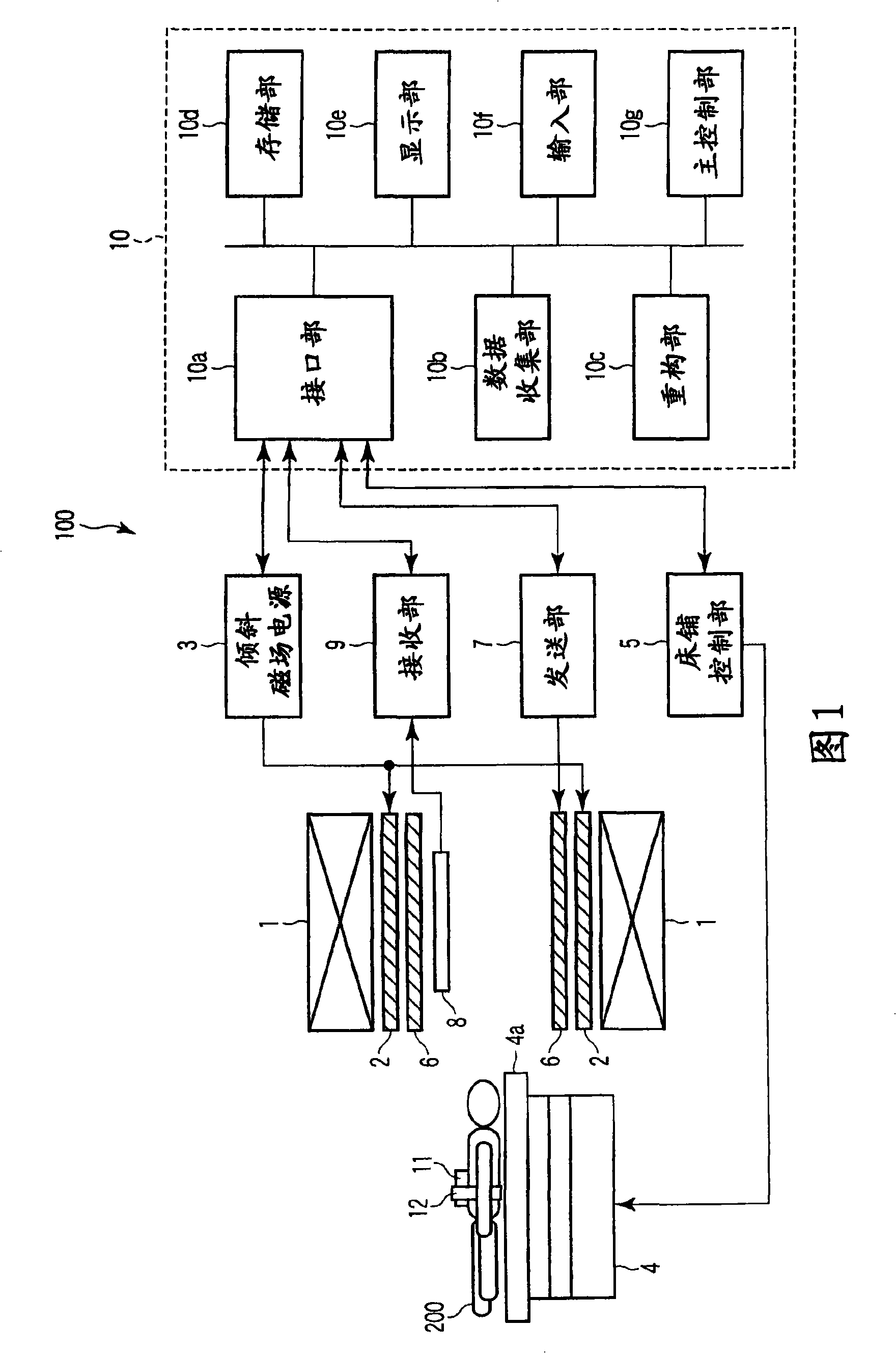
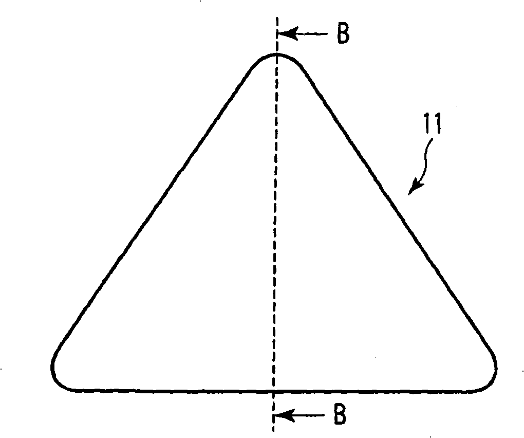
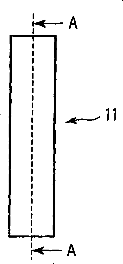
[0036] FIG. 1 is a diagram showing the configuration of a magnetic resonance imaging apparatus (MRI apparatus) 100 according to a first embodiment. This MRI apparatus 100 has: static magnetic field magnet 1, gradient magnetic field coil 2; Gradient magnetic field power supply 3; Bed 4; Bed control part 5; Send RF coil 6; And respiratory suppression pad 11.
[0037] The static field magnet 1 has a hollow cylindrical shape, and generates the same static magnetic field in the inner space. As the static field magnet 1 , for example, a permanent magnet, a superconducting magnet, or the like can be used.
[0038] The gradient coil 2 has a hollow cylindrical shape and is arranged inside the static field magnet 1 . The gradient magnetic field coil 2 is a combination of three coils corresponding to X, Y, and Z axes that are perpendicular to each other. The above-mentioned three coils of the gradient magnetic field coil 2 are individually supplied with current from the gradient magne...
no. 2 Embodiment approach
[0066] The configuration of the MRI apparatus according to the second embodiment is the same as that of the MRI apparatus 100 shown in FIG. 1 . The MRI apparatus according to the second embodiment is different from the MRI apparatus 100 in that a respiration suppression pad 13 is provided instead of the respiration suppression pad 11 .
[0067] Figure 4A It is a plan view showing the structure of the breathing suppression mat 13 . Figure 4B It is a side view showing the structure of the breathing suppression mat 13 . again, in Figure 4A , 4B in, for with Figure 2A-2D The same symbols are assigned to the same parts, and detailed description thereof will be omitted.
[0068] Such as Figure 4A , 4B As shown in , the breathing suppression pad 13 includes a rigid member 11a, an elastic member 11b, a cover 11c, a pressure sensor 13a, and a vibrating portion 13b. Furthermore, although in Figure 4A , 4B The illustration is omitted in , but the respiratory suppression p...
no. 3 Embodiment approach
[0075] The configuration of the MRI apparatus according to the third embodiment is the same as that of the MRI apparatus 100 shown in FIG. 1 . The MRI apparatus according to the third embodiment is different from the MRI apparatus 100 in that a respiration suppression pad 14 is provided instead of the respiration suppression pad 11 .
[0076] Figure 7A It is a diagram showing the appearance of the respiratory suppression pad 14 under the line of sight along the body axis direction of the subject 200 . Figure 7B It is a diagram showing the appearance of the respiratory suppression pad 14 under the line of sight from the subject 200 side. again, in Figure 7A , 7B in, for with Figure 2A-2D or Figure 4A , 4B The same symbols are assigned to the same parts, and detailed description thereof will be omitted.
[0077] Such as Figure 7A , 7B As shown in , the breathing suppression pad 14 includes a rigid member 11a, an elastic member 11b, a cover 11c, a vibrating portion...
PUM
 Abstract
Description
Claims
Application Information
 - R&D
- Intellectual Property
- Life Sciences
- Materials
- Tech Scout
- Unparalleled Data Quality
- Higher Quality Content
- 60% Fewer Hallucinations
Browse by: Latest US Patents, China's latest patents, Technical Efficacy Thesaurus, Application Domain, Technology Topic, Popular Technical Reports.
© 2025 PatSnap. All rights reserved.Legal|Privacy policy|Modern Slavery Act Transparency Statement|Sitemap|About US| Contact US: help@patsnap.com


