
Adjustable laser coaxial powder feeding nozzle

A coaxial powder feeding and laser technology is applied in the field of laser coaxial powder feeding nozzles and nozzles for laser metal direct manufacturing, which can solve the problems of low powder utilization rate and poor powder convergence effect, so as to improve the cooling effect and promote powder production. Convergence, to meet the effect of different requirements

Inactive Publication Date: 2010-06-16
XI AN JIAOTONG UNIV
View PDF5 Cites 5 Cited by
  • Summary
  • Abstract
  • Description
  • Claims
  • Application Information

AI Technical Summary

Problems solved by technology

[0005] In view of the fact that the laser metal direct manufacturing puts forward higher requirements for the coaxial powder feeding nozzle, the powder sent by the coaxial powder feeding nozzle is required to be more evenly distributed in the circumferential direction and has good convergence: in order to prolong the service life of the nozzle, it is required to The axial powder feeding nozzle has a good cooling effect; therefore, the purpose of the present invention is to overcome the defects of the existing nozzles in the laser cladding process, such as poor powder convergence effect and low powder utilization rate, and provide a powder cavity, air cavity and The focus-adjustable laser coaxial powder feeding nozzle has good powder convergence effect, high powder utilization rate and good water cooling effect. The whole nozzle structure design is reasonable, the processing technology is good, and the operation is convenient.

Method used


Image

  • Adjustable laser coaxial powder feeding nozzle
  • Adjustable laser coaxial powder feeding nozzle
  • Adjustable laser coaxial powder feeding nozzle

Examples


Embodiment Construction

[0022] The present invention will be further described in detail below with reference to the drawings and embodiments.

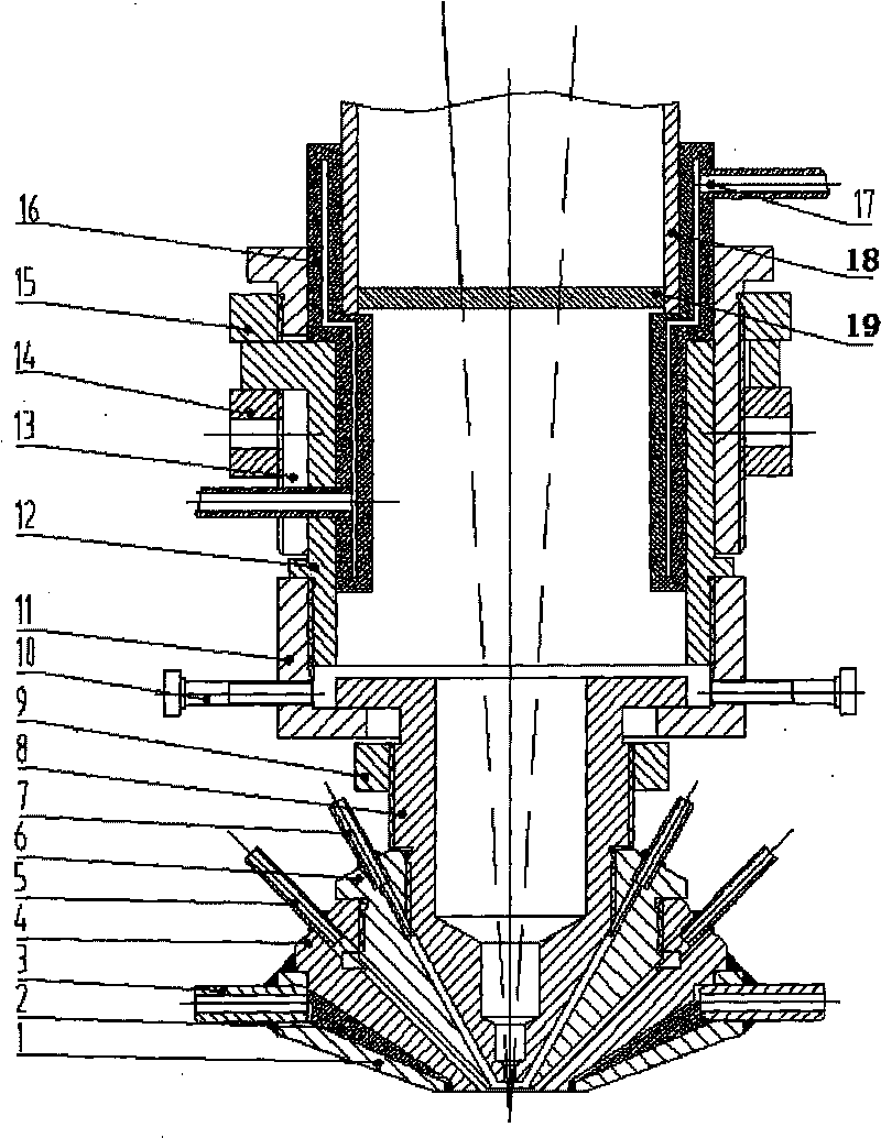
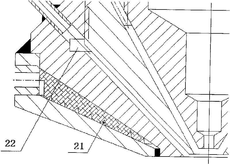
[0023] As attached figure 1 , figure 2 with image 3 As shown, the feature of the present invention is that the lower part of the coaxial powder feeding nozzle is composed of a nozzle water cooling jacket 1, a protective air jacket 4, a powder cavity jacket 6 and a laser jacket 8. The upper part of the coaxial powder feeding nozzle is composed of a centering adjustment base 11. Lifting inner and outer sleeves 12, 13, protective mirror water cooling jacket 16 and two screw clamps. The nozzle water cooling jacket 1 is welded with cooling water inlet and outlet pipes 3 on its cylindrical part. The nozzle water cooling jacket 1 and the protective air jacket 4 constitute a water cooling cavity. In order to prevent the "short circuit" phenomenon of the cooling water in the water-cooled cavity, a water diversion spiral block 2 is set in the water-cooled cavity. The ...


PUM

PropertyMeasurementUnit
diameteraaaaaaaaaa
thicknessaaaaaaaaaa

Abstract

The invention discloses an adjustable coaxial laser nozzle for feeding powder, comprising a laser head, a protection lens, a water-cooling sleeve for the protection lens and a column laser cavity arranged at the upper part, a coaxial conical laser cavity which is formed by the inner layer of a laser sleeve in the middle part; wherein, a powder cavity, a secondary external protective cavity and anexternal water-cooling cavity are arranged on the lower part of the external part of the laser sleeve; the powder cavity is formed between the laser sleeve and a power cavity sleeve screwed together;the secondary external protective cavity is formed between the powder cavity and a protective air casing screwed together; the powder cavity and the protective air casing are screwed together and adjustable between 1mm to 3mm; 4 to 6 power transmitting pipes and 4 to 6 air tubes are respectively positioned around the top parts of the cones of the powder cavity and the protective air cavity. The adjustable coaxial laser nozzle for feeding powder has the advantages that the focus length of the focus lamp fit for the coaxial powder-feeding nozzle is between 100mm to 300mm, which ensures convenient assembly and disassembly, even velocity, flexible adjustment of the powder converge diameter, and convenient changeable lower coaxial conical parts (the powder cavity, the air casing and the water cavity).

Description

Technical field [0001] The invention relates to a nozzle for laser metal direct manufacturing, in particular to a laser coaxial powder feeding nozzle, which belongs to the fields of laser processing and laser rapid manufacturing. Background technique [0002] Laser metal direct manufacturing technology combines rapid prototyping technology and laser cladding technology, and is an integration of the basic principles of rapid prototyping and the essence of laser processing technology. Based on the "discrete-stack" forming principle. First, generate a 3D CAD model of the final functional part in the computer; then slice the model in layers with a certain thickness, and control the forming system to use a laser coaxial powder feeding nozzle to scan the stacked material layer by layer according to the contour trajectory; finally form a 3D net shape entity Components. [0003] At present, there are three main powder supply methods in laser metal direct manufacturing technology: powder ...

Claims


Application Information

Patent Timeline
Patent Type & Authority Patents(China)
IPC IPC(8): B22F3/105
Inventor 张安峰孙哲李涤尘赵万华卢秉恒
Owner XI AN JIAOTONG UNIV
Learn More