Light filter and liquid crystal display device using the same

An optical filter and optical density technology, applied in the field of optical filters, can solve problems such as filter performance degradation, and achieve the effect of suppressing diffraction phenomenon and reducing display performance degradation.

Active Publication Date: 2008-09-10
FUJIFILM CORP
View PDF14 Cites 17 Cited by
  • Summary
  • Abstract
  • Description
  • Claims
  • Application Information

AI Technical Summary

Problems solved by technology

In the optical filter of this structure, diffraction or scattering of light occurs at the boundary between the light-shielding area and the transmission area, and there is a problem that the performance of the filter decreases.

Method used


Image

  • Light filter and liquid crystal display device using the same
  • Light filter and liquid crystal display device using the same
  • Light filter and liquid crystal display device using the same

Examples


Embodiment

[0183] Hereinafter, the present invention will be described in more detail based on examples. Materials, usage amounts, ratios, processing contents, processing procedures and the like shown in the following examples can be appropriately changed unless departing from the spirit of the present invention. Therefore, the scope of the present invention is not limited to the specific examples shown below.

[0184]

[0185] ・Production of color filter (CF)

[0186] -Manufacturing of Halftone Masks for Black Matrix-

[0187] make Image 6 Halftone photomask shown. The halftone mask is a photomask in which the part corresponding to the pattern of the colored layer is a light-shielding part, the part corresponding to the center of the black matrix is ​​a transparent opening part, and the part corresponding to the end part of the black matrix is for halftone. The length of the width of the opening portion is 30 μm, the length of the width of the light-shielding portion is 50 μm, a...

Embodiment 1

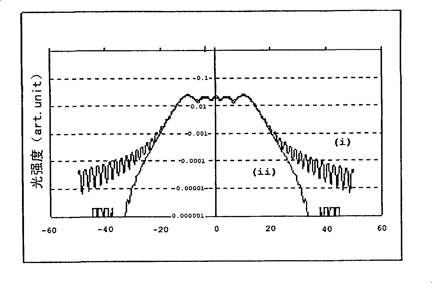
[0218] Compared with the liquid crystal display device of the comparative example, the liquid crystal display device of Example 1 has a reduced brightness in a black screen state, thereby increasing the contrast ratio from 1614 to 1754. This result can be understood as the result of the figure 2 This is because the diffraction at the boundary between the light-shielding region and the transmissive region of the color filter is reduced in Example 1, which is clear from the comparison of (i) and (ii).

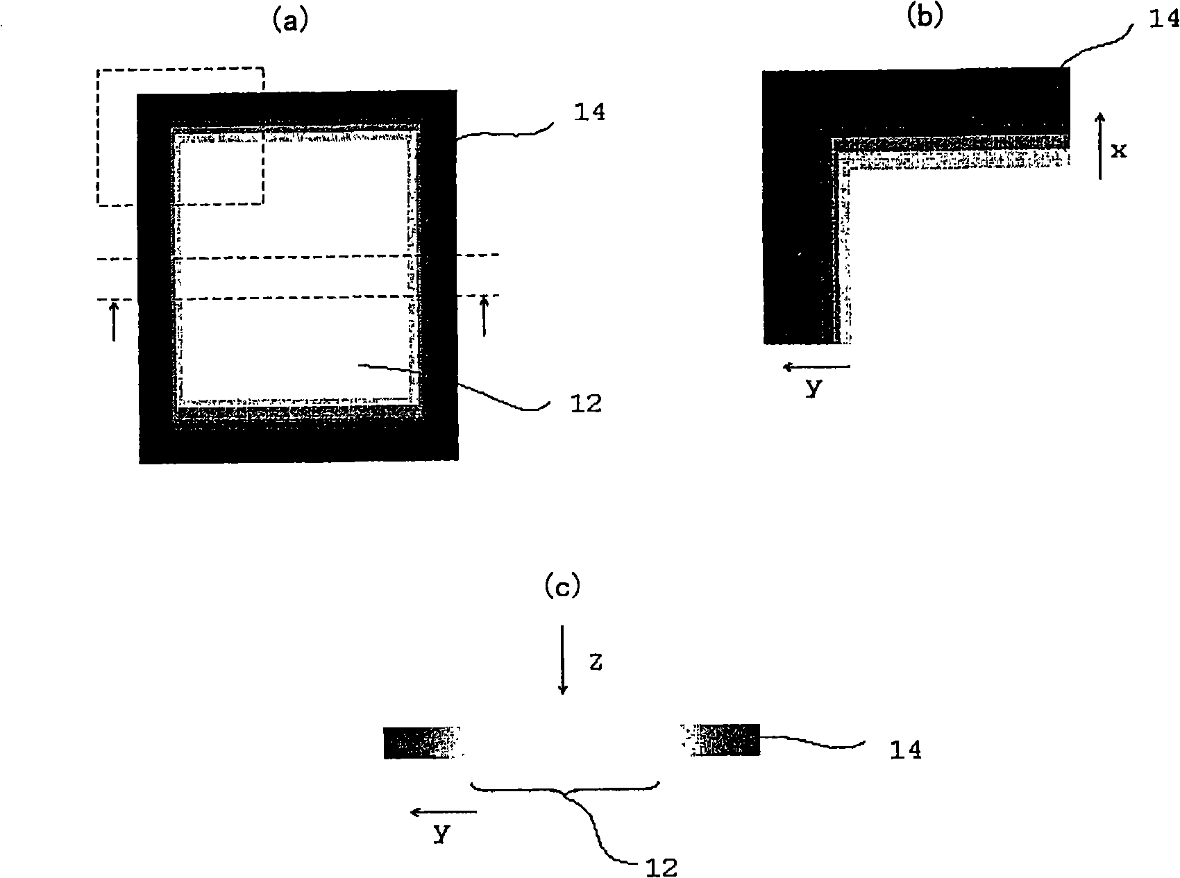
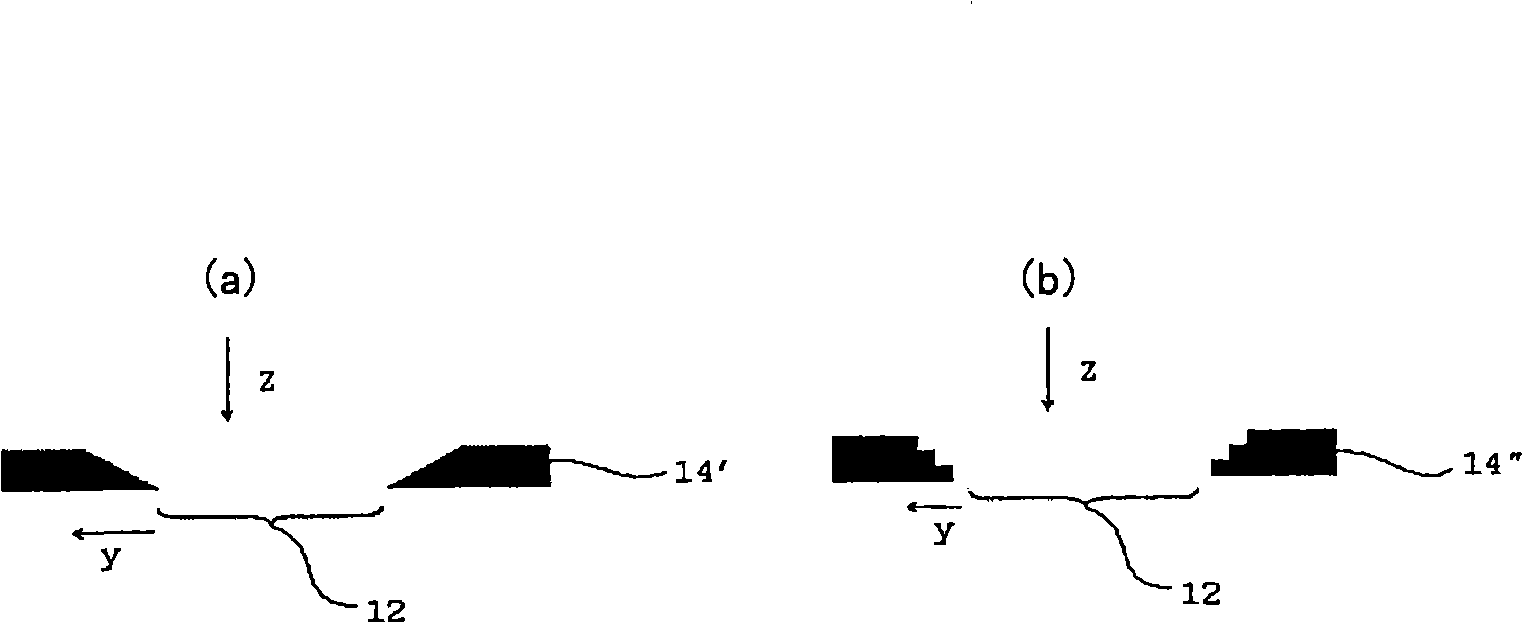
[0219] Additionally, for image 3 (a), (b) and Figure 4 The liquid crystal display device of the black matrix shape of (a) was also evaluated, and as a result, the improvement of contrast was confirmed similarly.


PUM

PropertyMeasurementUnit
particle diameteraaaaaaaaaa
acid valueaaaaaaaaaa

Abstract

The invention provides an optical filter having a light-transmitting region of transmitting light having a predetermined wavelength and a light-blocking region disposed adjacent to the light-transmitting region to block out the light, wherein the light-blocking region has an optical density gradation relative to light in the normal direction, from the contact point to the light-transmitting region along an in-plane direction, and the optical density is the smallest at the contact point to the light-transmitting region.

Description

technical field [0001] The present invention relates to an optical filter such as a color filter, and a liquid crystal display device using the same. Background technique [0002] An optical filter is a member having a function of absorbing only light of a specific wavelength and transmitting light of other wavelengths, and is used in various optical elements such as display elements. For example, in a full-color liquid crystal display device, a color image is displayed by combining light of three primary colors of red, blue, and green using color filters. Many optical filters such as color filters have a structure in which a transmission region that transmits light of a predetermined wavelength and a light-shielding region that blocks light are arranged in a predetermined pattern. In the optical filter having this structure, light is diffracted or scattered at the boundary between the light-shielding region and the transmissive region, and there is a problem that the perfo...

Claims


Application Information

Patent Timeline
Patent Type & Authority Applications(China)
IPC IPC(8): G02B5/20G02F1/1335
CPCG02B5/205G02F1/133512G02F2001/133388G02F1/133388
Inventor 海鉾洋行实藤龙二齐藤之人
Owner FUJIFILM CORP
Why Eureka
Try Eureka